Surface Mount Technology (SMT) PCB Assembly Service
Surface mount technology attaches electrical components to the surface of a printed circuit board that does not utilize leads in feed-through holes. It is an innovative trend in the field of Printed circuit board assembly.
JHYPCB provides a one-stop service from PCB production and component procurement to turnkey surface mount PCB assembly.
Home » PCB Assembly » SMT PCB Assembly
Advanced PCB Assembly Technology
Printed Circuit Boards (PCBs) have changed the concept of soldering components with wire and creating a complicated and unreliable circuit. PCBs are very compact and offer reliable performance for a very long time. They take up very little space and deliver the expected results.
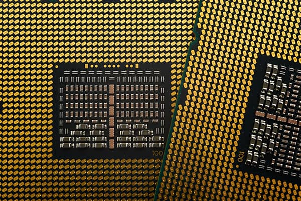
Nowadays, PCBs are used in almost every industry. Every product that requires some components and their interconnection uses a PCB. PCBs have gone through many changes in the past few decades. There have been many advancements, improvements, and new technologies. One of the leading PCB technologies is surface mount technology. It has supreme importance because it has further reduced the size of PCBs. The components used in the surface mount technology are minimal; the smallest SMD (surface mount device) has a dimension of 0.6mm x 0.30mm. SMT technology has significantly impacted the PCB industry and is widely used nowadays.
Table of Contents: SMT PCB Assembly Service
SMT PCB Assembly Supplier
What is SMT PCB Assembly?
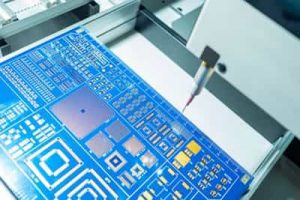
Surface Mount Technology is a specific technology for PCB assembly service. The components in this technology are directly mounted on the surface of the PCB without any holes/drilling. There are special components used for this technology that are called Surface Mount Devices. The components are placed over the PCB that already has conduction paths, and finally, the components are soldered in a reflow oven. They are directly attached to the board and perform better than Through-hole Technology (THT).
SMT PCB assembly is an easy and quick technique to make reliable circuit boards. The components are very compact, so the PCB is very small. SMT PCB assembly is widely used because it is a quick and better alternative to THT.
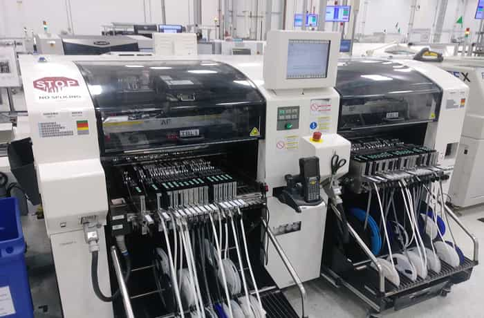
SMT Assembly Capability of JHY
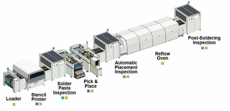
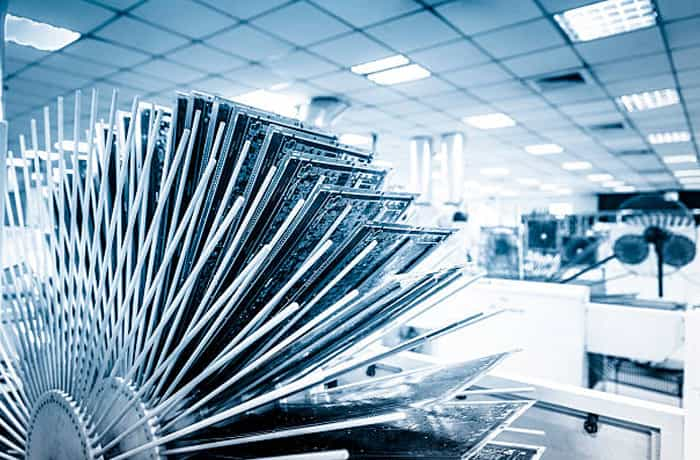
JHY offers high-quality and highly reliable PCB assembly service. Our PCB assembly factory has 8 fully automatic high-speed surface mount production lines and uses the most advanced SMT PCB assembly equipment. Including automatic board loading machine, automatic solder paste printing machine, solder paste thickness detector (SPI, Solder Paste Inspection), multi-temperature zone reflow soldering machine, optical inspection equipment (Automatic Optical Inspection), X-ray inspection machine, baking machine, and PCB stencil cleaning machine, etc. To meet the SMT assembly requirements of customers to the greatest extent, JHY can accept precision electronic components mounting like 0201 components, 0.4mm Pitch BGA, and QFN.
Combining quality and cost-effectiveness, JHY has become the leader in SMT PCB assembly services. With our extensive experience in various PCB assembly fields, we have become a trusted partner for customers worldwide with unmatched turn-around times and flexible options.
SMT PCB Assembly Capabilities
- Low-to-high Volume Assembly
- Single and Double-sided Assembly
- Mixed Technology
- Smallest components 01005, 0201, 0402
- Assemble 0.25mm fine-pitch parts
- Leadless components, BGA, µBGA, LGA, package on package, etc.
- PCB Types: Rigid PCB, Flexible PCB, Rigid-flex PCB
- PCB Shape: Any
- Quality Grade: IPC Class 2 | IPC Class 3
- No MOQ
- Capacity: SMT SMD 5 Million Points/day, Plug-in Welding 500,000 Points/day, 50-100 Models/day
- Free DFM and DFA Check
SMT Assembly Testing and Inspection Capabilities
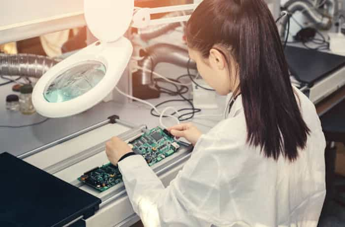
JHY makes it mandatory to perform visual inspections to see if there are any missing or misaligned components or issues with solder bridging. Besides manual reviews, we also use SMT inspection machines for this purpose.
- Automated Optical Inspection
- Solder Paste Inspection
- First Article Inspection
- X-ray Testing
- In-circuit Testing
- Functional Testing
Applications of SMT PCB Assembly Services
As the Surface Mount Technology picked up momentum, there has been a constant increase in the usage of this technique across many industries. The market share of SMT assembly services has been increasing by the day.
Some of the industries that utilize JHY for SMT PCB assembly are –
- Aerospace
- Consumer Electronics
- Defense
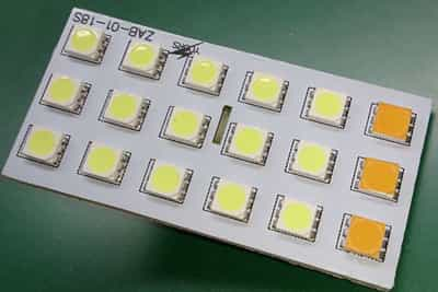
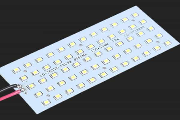
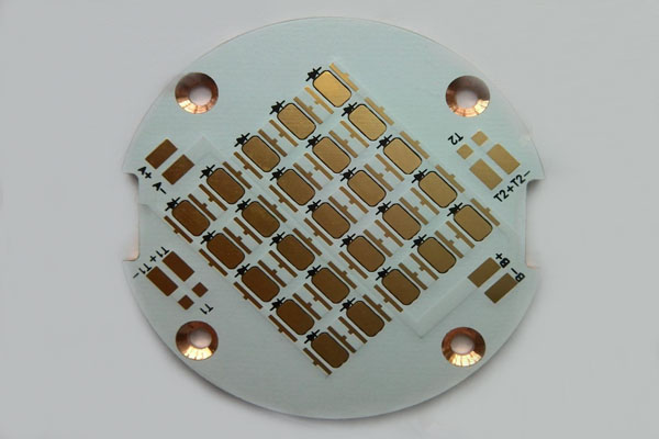
- LED components
- Medical and Health care
- Transport and Automotive Electronics
- Telecommunication & Mobile communications
What is the Difference Between SMT and SMD?
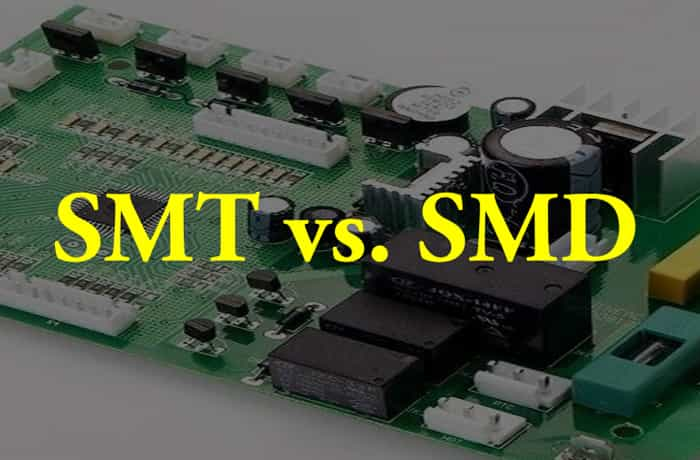
Often buyers get confused with these two terms: SMT and SMD. These terms are often used interchangeably, but they are different.
SMT stands for Surface Mount Technology, a technology or a method of placing components directly on the PCB. On the other hand, SMD stands for Surface Mount Devices that are components or devices used in the Surface Mount Technology. The devices are components, such as resistors, transistors, and LEDs. Both terms have a relationship, but they refer to different things. Long story short, SMT is a process while SMDs are the physical components.
What is the Difference Between SMT and THT?
SMT and THT are two different technologies for mounting electronic components on the PCB board. Both are different and have their distinct advantages and disadvantages.
Traditional through-hole Dual In-Line Package assemblies reached their limits in terms of cost, weight, volume, and reliability improvements. SMT allows more reliable assemblies with higher I/O, increased board density, and reduced weight, volume, and cost. The weight of printed circuit board assemblies (PBAs) using SMT is reduced because surface mount components (SMCs) can weigh up to 10 times less than their conventional counterparts and occupy about one-half to one-third of the space on the printed circuit board (PCB) surface. SMT also provides improved shock and vibration resistance due to the lower mass of components. The smaller lead lengths of surface mount components reduce parasitic losses and provide more effective decoupling.
THT is old technology and was widely used before SMT. THT components are a bit large as compared to their SMT counterparts. Thus, a THT PCB assembly is larger than an SMT PCB assembly. However, when the THT components are soldered, they can bear high mechanical and environmental stress. But SMT components cannot bear thermal and mechanical stress because they use less solder paste, which fails in the case of stress.
Advanced Learning: Solder Paste and Solder Paste Printing in SMT PCB Assembly
Nowadays, SMT is preferred over THT, but THT is still used where there is high heat and mechanical stress. There is also a Mixed technology that uses both SMT and THT. It is by far the best because the components suitable for SMT are placed via SMT and the others placed through THT. Such types of boards have the qualities of both technologies, making the PCB more reliable and cost-effective.
ADVANTAGES & DISADVANTAGES
The primary technical considerations for implementing SMT include surface mount land pattern design, PCB design for manufacturability, solder paste printing, component placement, reflow soldering, wave soldering, cleaning, and repair/rework. To achieve high-quality, reliable surface mount products, these areas must be studied and thoroughly understood. The smaller size of SMCs and the option of mounting them on either or both sides of the PCB can reduce board real estate by four times. A cost savings of 30% or better can also be realized through reduced material and labor costs associated with automated assembly.
Benefits of Surface Mounting Technology

Since the surface mounting component’s weight is 10 times less than their conventional counterparts and since they occupy 3 times less than the space required by the standard components, the size, weight, and volume of the printed circuit board assemblies using this technology are reduced considerably, without any reduction in reliability. Also, it allows improved shock and vibration resistance due to the lower mass of components.
The dominant benefit of surface mount technology is its compactness. It reduces the size of the PCB assembly and makes it lightweight. The component packages are very small; therefore, they take little space as compared to THT components. Furthermore, the components can be placed on both sides of the PCB. So, a large circuit can be made on a small board.
SMT offers reliable performance and optimum results. The process is carried out through machines, so the chances of errors are less. The soldering is also done by an automated process, so it is less prone to short circuits and other problems.
The cost of SMT PCB assembly is low because there is no need for holes. It saves time and effort, which reduces costs. Moreover, SMDs are small and can be transported easily. They require less space.
SMT reduces the time to assemble a PCB. There are surface mount technology machines that can place the component directly on the board. Moreover, there is no need for drilling, which also reduces the time. In the case of THT, most components are soldered manually or by other processes, but SMDs are picked and placed by machines and then soldered in the reflow oven. Almost every step is automated. Thus, the production of SMT PCB assembly is much faster than the THT PCB assembly.
Disadvantages of Surface Mounting Technology
The only disadvantage is the cost all the operations in this technology is carried out by machines, and since these machines are expensive, individuals cannot implement this.
There is very little solder applied to the SMT PCB assembly. Therefore, it cannot bear thermal and mechanical stress. These solder joints are likely to fail in case of heat cycles. So, SMT is not reliable for extreme environments.
There are fewer chances of errors because of the automated process, but it is difficult to trace if there is any. Finding errors in SMT PCB assembly is not easy. It requires special techniques to find errors.
Surface mount technology requires expertise. There are trained people to carry out the process successfully. Moreover, the surface mount technology machinery is quite expensive.
Surface Mount Technology Types and Process Flow
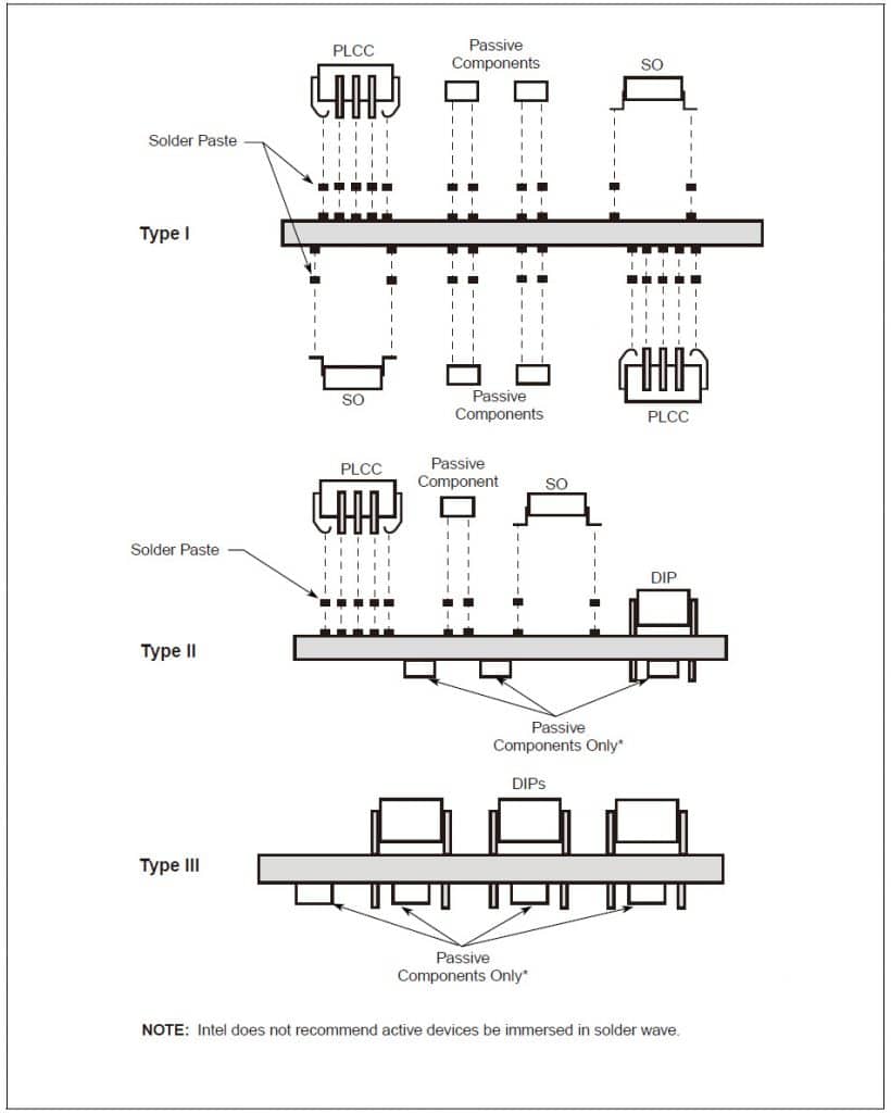
Surface Mount Technology (SMT) replaces DIPs (or THT, Through-hole Technology) with surface mount components (SMCs). The assembly is soldered by reflow and/or wave soldering processes depending on the mix of surface mount and through-hole mount components. When attached to PCBs, both active and passive SMCs form three major types of SMT assemblies, commonly referred to as Type 1, Type II, and Type III (As shown on the right).
Type I is a full SMT PCB board with components on one or both sides of the circuit board.
Type II is probably the most common type of SMT board. It has a combination of through-hole components and SMT components. Often, surface mount chip components are located on the secondary side of the Printed Circuit Board (PCB). Active SMCs and DIPs are then found on the primary side. Multiple soldering processes are required.
Type III assemblies are similar to Type II. They also use passive chip SMCs on the secondary side, but on the primary side only DIPs are used.
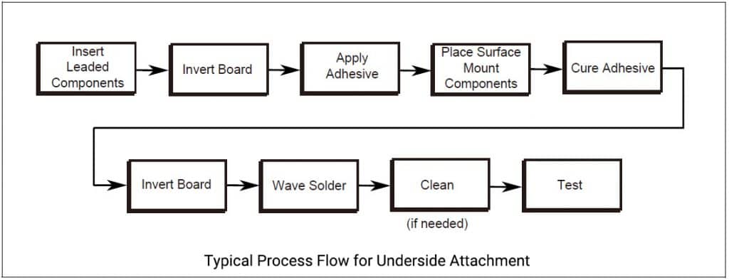
Typical Process Flow for Underside Attachment (Type III SMT)
Leaded components are inserted, usually by automatic equipment. The assembly is turned over, and adhesive is applied. Next, passive SMCs are placed by a “pick-and-place” robot, the adhesive is cured, the assembly is turned over, and the wave-soldering process is used to solder both leaded and passive SMCs in a single operation. Finally, the assembly is cleaned (if needed), inspected, repaired if necessary, and tested. For this type of board, the surface mount components used are chip components and small pin count gull wing components.
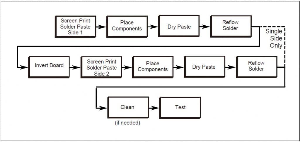
Typical Process Flow for Total Surface Mount (Type I SMT)
For a single sided type I, solder paste is printed onto the board and components are placed The assembly is reflow soldered and cleaned (if needed). For double-sided Type I, the board is turned over, and the process sequence just described is repeated.
Type II assemblies go through the process sequence of Type I SMT followed by the sequence for Type III. In general practice, only passive chip components and low pin count gull wing components are exposed to solder wave immersion.
Note: Source by Inter Leaded Surface Mount Technology (SMT)
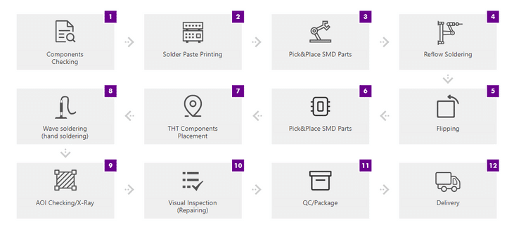
Surface Mount Technology Assembly Process
The process of surface mount technology involves some important steps. It starts all the way from PCB designing and ends at the final testing of PCBA.
1) PCB Designing
PCB designing is the responsibility of the buyer. He needs to design the PCB according to the requirements. During designing, appropriate SMDs are selected. PCB substrate, number of layers, solder mask, silkscreen, and everything is chosen. After designing, Gerber files, BOM, and other important files are provided to the PCB manufacturer. From this stage, the work of the PCB manufacturer starts.
2) Design for Manufacturability (DFM) Inspection
Most designers are not aware of the PCB assembly process. So, they don’t understand the technicalities and complications. This is the reason their design could have some problems. But DFM inspection is carried out at our end. Our experts check the files provided by the customer and ensure everything is up to the mark. It reduces delays in the manufacturing process.
DFM check is an essential step because errors and problems are detected before the start of manufacturing. These problems are solved after consulting the customers. After that, the manufacturing process is carried out smoothly. Not only the delivery time is ensured, but the manufacturing cost is also reduced.
The components are bought according to the BOM. So, BOM is an essential document for PCBA. If there is something unavailable, the component could be replaced with a similar one after consulting the buyer. The components are shipped from different vendors, so this step requires a few days.
4) PCB Fabrication
The procurement of components requires time. Until then, the PCB is fabricated. The bare board is fabricated according to the requirement of the buyer. These requirements are discussed at the time of placing the order. The buyer needs to provide the design and discuss the type of PCB base material, surface finish, solder mask, silkscreen, etc.
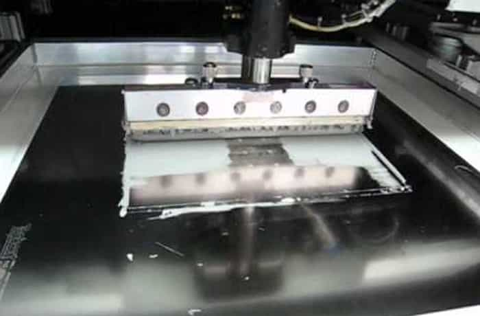
5) Application of Solder Paste
For soldering the SMDs, solder paste is applied. The paste is applied to the required areas of the board only. Therefore, a stainless-steel stencil is used. The stencil is placed over the board, and solder paste is applied. The paste enters every hole of the stencil and covers the required area. Once you remove the stencil, you have solder paste in the required locations.
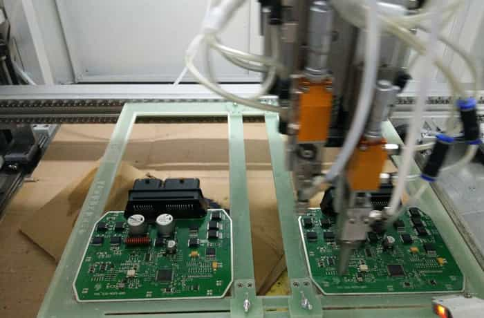
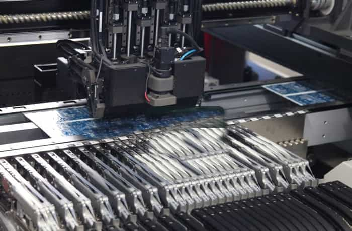
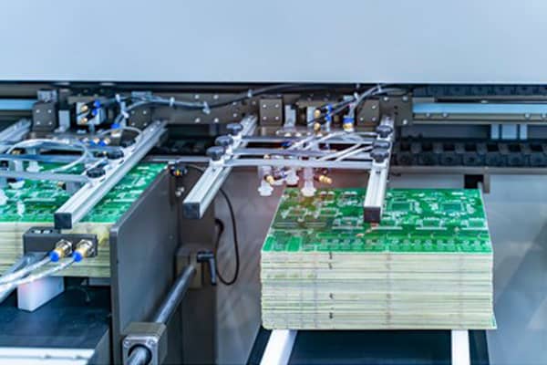
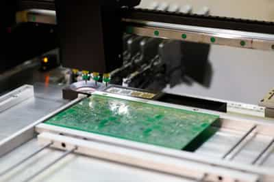
6) Pick and Place
This is an automated process of picking and placing the SMDs on the PCB. The PCB is held in a machine, and the components are picked and placed in specific places. This automatic process makes the manufacturing process quicker. There is no need to place and solder the components manually. The process is done with the help of a robotic arm, so it can be carried out round the clock. It also reduces the probability of errors.
The components are placed where they should be. The XY coordinate of the components is provided using the Pick and Place file.
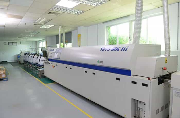
In pick and place, the components are only placed in the right places. Then, they are soldered using reflow soldering. The PCB is passed through a reflow oven, which melts the solder paste and connects the SMDs to the board.
The PCB is placed over a conveyor belt and passed through the oven. So, there is no manual work needed. After passing through the hot oven, the PCB is cooled.
8) Inspection
Inspection is an important step to make sure the PCB is up to the mark and ready to provide the desired results. The problem can be with soldering. There could be short circuits or open circuits. Therefore, inspection is necessary to detect the flaws and errors.
First, the inspection is carried out manually. This is not necessary, but some errors can be detected by the naked eye. After manual inspection, AOI (Automatic Optical Inspection) or X-ray Inspection is carried out.
Automatic Optical Inspection (AOI) is a quick method of detecting errors. There are cameras that visualize the PCB. The visual image can also be seen on monitors. The cameras are placed at different angles to analyze every part of the PCB. But this method cannot analyze the connections under the components. It cannot be used for the inspection of a multilayer PCB.
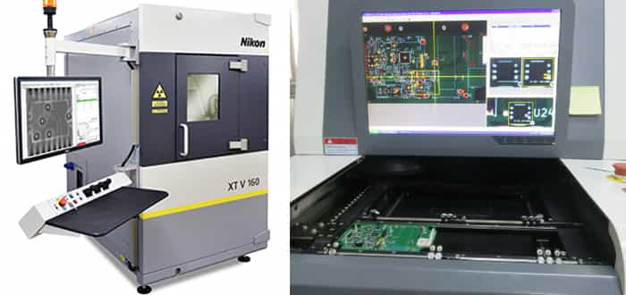
X-ray Inspection is an advanced method. It can be used to see the connections under the components and the layers of the PCB. X-rays pass through the board and provide a picture on the screen. It can detect minor faults in the PCBA.
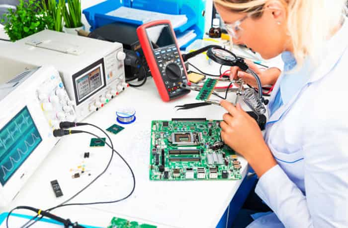
9) Final Test
After inspection, the PCBA is tested to check the results that it is offering. This is a functionality test that ensures the components are working as expected. It is the last process of the surface mount manufacturing process. After this, the PCBA is shipped to the customer.
Click here to learn more about”Testing & Inspection Methods For PCB And PCBA.“
SMT PCB Assembly FAQs
The PCB assembly pricing includes setup fee, stencil fee, assembly fee and components cost. We do not charge any other labor fees.
Yes. We provide full turnkey PCB assembly or customer to provide PCSs or components.
- Gerber file, it is used for PCB production.
- BOM file(Bill of Materials).
- CPL file(Component Placement List / Pick & Place File (PNP) file), it is used by our automated SMT Assembly machines to determine where each part should be located on the board.
Send Gerber file and BOM/CPL files to sales@pcbjhy.com to get SMT PCB assembly quote.
No, you don’t have to. We’ll add fiducial marks for SMT assembly.
Assembly turn-time begins immediately after the PCB turn-time and 90% of SMT orders can be finished within 24 hours, 48 hours at most. We prepare all necessary material for SMT assembly like SMT engineering data, components and solder paste stencil while PCB production, so assembly can begin immediately after completing the PCB fabrication.
SMT PCB Manufacturer in China
JHYPCB is a PCB and PCBA manufacturing company based in China. We offer the best quality and fast turnaround without the restrictions of minimum orders.
We are fully compliant with international standards. We are ISO, RoHS, and UL certified. Our strict quality management ensures high-quality PCB and PCBA. We can offer prototype PCB assembly service, through-hole PCB assembly, and full turnkey SMT PCB assemblies. We also offer a DMF check to ensure timely delivery and a smooth manufacturing process. For more information, feel free to contact us.
Recommended PCB Fabrication Services
Related Reading
- How to Choose the Right PCB Manufacturer and Supplier
- Quick turn PCB fabrication and assembly services in China
- 6 Tips For Looking For A PCB Prototype Manufacturer
- Reasons for Rapid PCB Prototype Manufacturing
- How to Store PCB and PCBA?
- How long can PCBA finished products be stored?
- What is the difference between wave soldering and reflow soldering?
- The Production Process and Specifications of PCB SMT stencil
- How To Clean The Solder Paste On SMT Stencil
- The Main PCB Assembly process Steps
- PCB Assembly Capability
- How to Use PCB Stencil-Step by Step Guideline
- Materials Used in Surface Mount Technology
- The Advantages and Disadvantages of Surface Mount Technology