What is SMT(Surface Mount Technology)
SMT (Surface Mount Technology) is a series of comprehensive engineering technologies involving microelectronics, precision machinery and instruments, automatic control, welding, and material inspection. SMT is the mainstream of secondary packaging in microelectronics technology, gradually replacing the early through-hole assembly in PCB assembly.
SMT technology has the advantages of high production efficiency and good electrical interconnection performance. It can achieve a higher assembly density of electronic components per unit area of printed circuit boards.
SMT technology meets the needs of the modern electronics industry and occupies a leading position in the production of the modern electronics industry.
The most critical process in SMT technology is the reflow soldering process. The quality control of the reflow soldering process determines the quality of the terminals produced by SMT because defects caused by the design of surface mount components and printed circuit boards, solder paste printing, and component placement will eventually be concentrated in the reflow soldering process.
If there is no reasonable and feasible reflow soldering process control, the full process control will become meaningless.
Therefore, reflow soldering process control is the key to SMT quality control.
The process control of reflow soldering is manifested as the control of the reflow curve in the process. The curve of the solder joint temperature between the printed circuit board and the surface mount component overtime must meet specific control requirements.
SMT defects caused by improper reflow soldering curve include component burst/crack, component warpage, bridging, virtual soldering, PCB delamination or blistering, etc. These defects can be avoided by improving the reflow profile.
Therefore, good optimization of the reflow temperature curve can achieve better SMT placement quality.
The Working Principle of Reflow Oven
1. The Preheating Zone: The function of this zone is to heat the PCB at room temperature as soon as possible to reach the second set goal, but the heating rate should be controlled within an appropriate range. If the temperature rises too fast, thermal shock will occur, and the PCB and components are easily damaged; if the temperature rises too slowly, the flux activity will affect the welding quality. Due to the faster heating rate in this zone, the temperature difference between the components in the latter part of the temperature zone is relatively significant. To prevent thermal shock from damaging the components, it is generally specified that the maximum heating rate is 4°C/sec. Usually, the temperature rise rate is set to 1-3 degrees per second.
2. The insulation zone (The Constant Zone): refers to the area where the temperature rises from 120°C to 160°C. The primary purpose of this temperature zone is to make the temperature of each component on the PCB tend to be uniform and minimize the temperature difference. Give enough time in this area to make the temperature of the more significant component catch up with the minor component and ensure that the active ingredient of the flux in the solder paste is fully functional. At the end of the heat preservation zone, the oxides on the pads, solder paste balls, and component pins should be removed, and the temperature of the entire printed board will reach equilibrium. It should be noted that all components on the PCB should have the same temperature at the end of this section; otherwise, entering the reflow section will cause various bad soldering phenomena due to the uneven temperature of each part, so the time in this section should be controlled. . After many experiments, we set the time range of this zone to 60-100 seconds.
3. The reflow zone (The high-temperature zone): In this zone, the heater temperature is set to the highest so that the component’s temperature rises to the peak temperature quickly. The soldering peak temperature varies with all solder pastes in the reflow section. Generally, it is recommended to add 20-40°C to the melting point of the solder paste. For 63Sn/37Pb solder paste with a melting point of 183°C, the peak temperature is generally 210-230°C, and the reflow time should not be too long to prevent adverse effects on the PCB. The ideal temperature profile is that the “tip area” that exceeds the melting point of the solder covers the smallest volume and is symmetrical. Under normal circumstances, the time range exceeding 200°C is 30 seconds, but it depends on the specific situation. If there are other defects such as false welding, cold welding, etc., it can also be extended appropriately.
4. The cooling zone: The molten solder in this zone has thoroughly wetted the surface to be connected and should be cooled as fast as possible to help obtain bright solder joints with a complete profile and a low contact angle. Slow cooling will cause more decomposition products of PAD to enter the tin, resulting in dull and rough solder joints. It can cause poor soldering and weak solder joint bonding in extreme cases. The cooling rate of the cooling section is generally 3-10°C/sec, and it can be cooled to 75°C. Generally, an ion fan is used for forced cooling
Click here to learn more about reflow soldering
Reflow Soldering Temperature Profile Modes
1. Warm up-keep Warm Mode
This is a traditional reflow soldering temperature curve mode
Rise quickly from the initial temperature to a specific preheating temperature in the range of 140-170℃ and keep it. TPHH-TPHL should be determined according to the capacity of the reflow oven (±10℃). Then the temperature is kept at about 40-120s as the preheating zone, then quickly heat up to the reflux zone, and then quickly cool into the cooling zone (the temperature change rate is required to be below 4°C/sec).
The characteristics of this model: Generally, a lower preheating temperature is used, so the temperature has less influence on the components (that is, the stress on the components is less), so the heating time is extended to achieve the activation of the flux. At the same time, because the temperature rises quickly from the preheating zone to the reflow zone, it is easy to deteriorate the soldering rheology and cause displacement, and the flux activation temperature is also lower.
Gradual Heating Mode
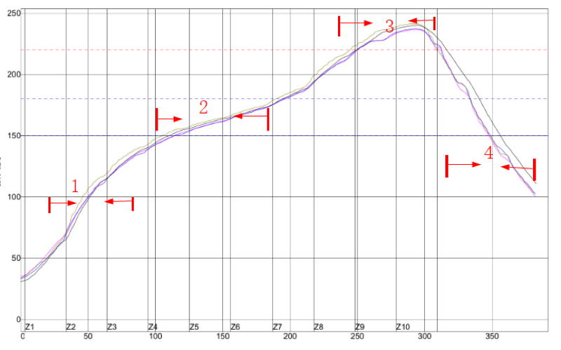
This is the current best reflow oven temperature curve.
Heat to about 175°C at a slower temperature rise rate (0.5-1°C/sec), then the gradient rises to about 180° within 20-30S, and then quickly rises to about 220° at 2.5-3.5°/sec, Z Then quickly cool down at no more than 4°C/sec. The main point of its control is to maintain a specific preheating temperature rise rate, and the end of preheating is close to the melting point temperature of tin.
Features of gradual heating mode
The components are not subject to drastic temperature changes, and the activation temperature of the flux can be set at a higher gear. Still, the activation time of the flux is short, and at the same time, the high preheating temperature makes the components affected by high temperature.
The difference between the above two reflow temperature curve modes is mainly reflected in the temperature curve part of the latter without plateau structure (i.e., constant temperature heating zone). Due to the difference in the heat absorption properties of the substrate structure and its components and the limitation of the device’s controllable heating rate, there will still be differences in temperature at different points of the substrate passing through the reflow oven. By means of a plateau form of equilibrium zone that reduces the temperature gradient, when the hot spot temperature is below the melting point of the solder, if the temperature is maintained for some time, the cold spot temperature will be able to catch up with it. After each element reaches the same temperature, another temperature rise program will make the element rise to the peak temperature, effectively avoiding local high-temperature coking.
On the other hand, when the former plateau structure is obtained, a rapid heating process will inevitably occur from room temperature to constant temperature preheating section and from constant temperature section to solder melting section. There is a close relationship between the uneven wetting on both sides of the part before the melting point, which causes warpage and other defects. Many SMT quality problems are expected to be prevented and eliminated by using a linearly increasing heating temperature between room temperature and the melting point of the solder.
Recommended Posts
What are the aspects of PCB Design For Manufacturing (DFM) and Design For Assembly (DFA)?
This article will introduce in detail about what is PCB Design For Manufacturing (DFM) And Design For Assembly (DFA).
Custom PCB Fabrication in China – Prototyping & Mass Production
At JHYPCB, a leading custom PCB manufacturer in China, we provide reliable solutions for all your prototyping, mass production, and assembly needs. Our state-of-the-art facilities, skilled team, and customer-centric approach ensure high-quality custom circuit boards delivered efficiently. Partner with us for a seamless journey from concept to fully functional product.
10 Tips To Improve PCB Design For Manufacturability
Through the Design For Manufacturability(DFM) of the printed circuit board, the design department and the production department can be effectively connected organically. The design, development, and production can be coordinated to unify the standards, realize production automation, and improve production efficiency.
Introduction to Aluminum PCB Manufacturing Process
An aluminum PCB is a printed circuit board that contains a thin layer of conductive dielectric material. Aluminum PCB is widely used in the LED lighting industry. Here we will explain the manufacturing process and process of aluminum PCB in detail.
What Is PCB OSP Surface Finish?
OSP refers to Organic Solderability Preservative. It is the leading PCB surface finishing coating option used by the PCB industry for protecting Copper surfaces and its features that are exposed from oxidation before the PCB is populated.
The Ultimate Guide to PCB Prototype Manufacturing: Everything You Need to Know
Looking for a reliable PCB prototype manufacturer? Look no further than JHYPCB. With years of experience and a commitment to quality, JHYPCB offers a comprehensive PCB prototype service that includes single-sided, double-sided, and multi-layered PCBs, as well as a variety of surface finishes and solder masks.


