What Files Are Used For PCB Manufacturing And Assembly?
The emergence of printed circuit board technology has managed to revolutionize the electronics industry. This could be due to its advantages which could be excellent shell life, it is re-workable, compact size and its low cost. Given all of these, it can be said that PCBs have become very popular amongst manufacturers of electronic devices in recent times.
The truth is that there are some factors that have been responsible for the success experienced by these circuit boards. A typical example is the files used in their manufacturing and assembly. These are data files that contain circuit board designs. This article will be aiming to explain some of the various files that are usually used for such purposes.
What Files Are Needed For PCB Manufacturing?
In this section, we will be looking at some of the materials or files that are used during the process of manufacturing PCBs. These could be:
- PCB Gerber files
- .BRD file
- NC Drill file
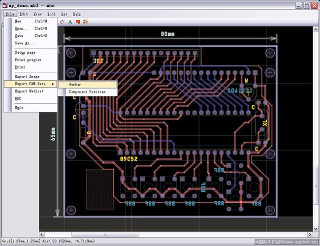
What is Gerber File?
Gerber is probably the most common file amongst others that are used in the manufacturing of PCB. Probably you must have heard of manufacturers talking about Gerber files before and wondered what it meant. There is nothing complicated about this since they mean ASCII files. These normally contain data that are Gerber-formatted. There is one unique feature of Gerber files that is worth mentioning. This is the fact that they aren’t subject to design rules or net connectivity. The same can also be said about component libraries.
This is an artwork (2-dimensional) that has the role of dictating the exact position where silkscreen, solder mask, or copper will be placed. It should be noted that just 1 Gerber file can‘t perform all the roles. For instance, if you have one PCB feature (one layer), information about such will be provided by one Gerber file. Therefore, if the board is 2-layered with each side having silkscreen, solder mask and copper, 6 Gerber files will be required.
It is fair enough to say that the Gerber file is the industry’s de-facto standard. This is due to how it is used in describing images on printed circuit boards. These could be drill data, legend, solder mask, copper layers and more.
There are three versions of Gerber in existence:
- Gerber X2: Gerber X1 and Gerber X2 are a subset of Extended Gerber. Gerber X2 is the latest Gerber file format.
- RS-274X: Also known as Extended Gerber, or X-Gerber format. It is a widely accepted Gerber file format and is commonly used.
- Standard Gerber: RS-274D is the old version, gradually being replaced by RS-274X.
The “Gerber Job File Editor” software can be downloaded from Ucamco’s website, and click here to learn more about the Gerber definition.
Learn more about”PCB Terminology Glossary“
Why provide the Gerber file to the PCB manufacturer?
Because electronic engineers and PCB engineers have a different understanding of PCB.
The GERBER files converted from the PCB factory may not be what you want.
For example, when designing PCB, you define the parameters of components in the PCB file, but you don’t want these parameters to be displayed on the PCB product. But if you don’t explain, the PCB factory will follow the instructions and leave these parameters on the PCB product.
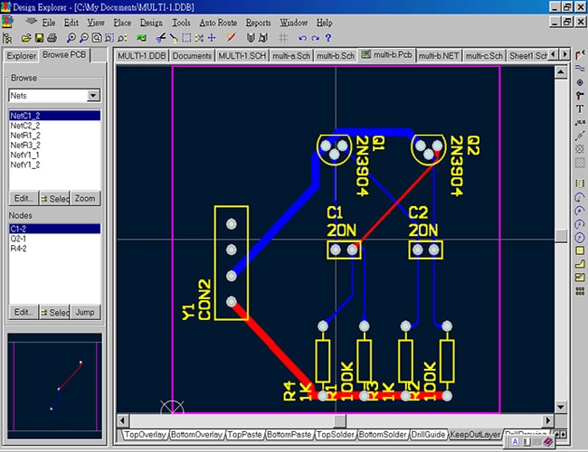
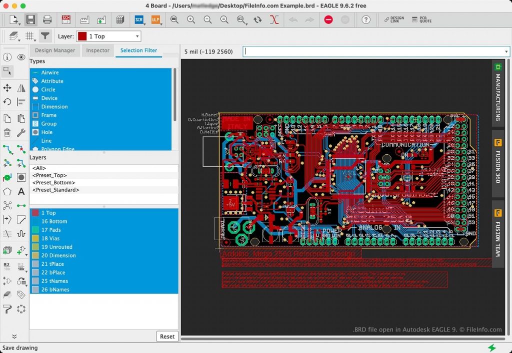
What Is .BRD File?
The first thing to note is that the.BRD file is actually a CAD file with XML format. This is a very important file that can’t be ignored during the manufacturing of PCB. It is a software or application that can help in designing of PCB templates. BRD is created by Autodesk EAGLE. It is possible for you to have such a file saved in Gerber drill data format. A simple way to understand BRD files is to view them as design files. These are usually compatible with Gerber-related files.
A CAD application is any tool which is used in the creation of PCB designs. In the same vein, BRD files are all about PCB drawings. The proprietary format is how they are usually encoded. This makes it quite difficult for them to be opened using third-party tools. For instance, Eagle encodes BRD files as “XML”. On the other hand, KiCad as well as Altium Designer usually have their PCB layouts saved in the form of plain text.
Today, there are different free and open-source programs which can be used in viewing or opening BRD files. These are OpenBoardview, RPG Toolkit, Allegro, Smart Charts Drug Development Suite and others.
NC Drill file
This is an acronym for numeric control drill file. When printed circuit boards are being manufactured, holes will have to be drilled. Of course, this has to be carried out without any form of guesswork. NC Drill file plays a crucial role in all of these. For instance, it is a type of file that ensures information about the whole drilling is provided. It is responsible for determining the positions where holes are supposed to be placed on a PCB. It can also pinpoint the sizes of holes that will make such a process successful.
For best results, it is always recommended that NC Drill files are created using a similar format as that of Gerber files. Of course, the role of an NC Drill file can hardly be overemphasized. This is because components must be mounted on printed circuit boards. Such is where these files will prove to be important. The default or ordinary format of NC Drill files is Excellon, a manufacturer of Computer Numeric Control (CNC).
Excellon is a format that is widely applied especially when it comes to standard CNC drilling as well as routing. This is due to how it can provide specific information about machines. Speed and drill feed are some typical examples of its roles.
Other PCB board making information.
Additional PCB production information includes:
- Quantity
- Board making instructions: impedance requirements, board thickness, copper thickness, solder mask colour (green, yellow, black, blue, red, white, purple, grey optional), surface finish process (HASL/lead-free HASL, Immersion Gold/Silver/Tin, OSP, etc. Silk Screen printing colour (white, black, yellow optional), IPC standard, special process requirements, panelization requirements, etc.
- Lead Time
- PCB material
JHYPCB PCB Manufacturing Capability
| Files Required | Specification |
|---|---|
| Files Required | The PCB Manufacturing files we can accept is: Gerber RX-274X, .brd, .pcb, .pcbdoc, etc. |
| If you also have the stack-up or impedance control or other information, feel free to send them together with the PCB manufacturing files. | |
| PCB Materials | Non-flame retardant board | flame retardant board | semi glass fiberboard | epoxy fiberglass board | high-frequency board | aluminum base board, etc |
| The Thickness of The Plate | 0.3mm | 0.5mm | 0.8mm | 1.0mm | 1.2mm | 1.6mm | 2.0mm, etc. |
| Mechanical Processes | Such as punching and cutting, CNC drilling and milling, palletizing process, V cutting, etc. |
| Solder Mask Colors | Green|Red|White|Black | Blue|Yellow|Orange|Purple|Gray|Transparent, etc. Matte: Green|Blue|Black, etc. |
| Surface Finishes | OSP|HASL|HASL Lead-Free (HASL LF)|Immersion Silver|Immersion Tin|Plated Gold|Immersion Gold(ENIG)|ENEPIG|Golden Finger+HASL|ENIG+OSP|ENIG+Golden Finger|OSP+Golden Finger, etc. |
| Special Requirements | To be provided upon special request. |
What Files Are Needed For PCB Assembly?
Some of the files for this process will be highlighted and explained. These are:
- BOM
- Centroid file
What Is BOM?
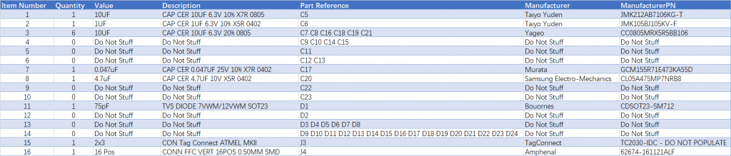
BOM is simply a short form of a bill of material. It is actually a centralized source where information used in manufacturing a product is provided. This is a file which provides or outlines the process required for assembling of printed circuit boards. Normally when PCBs are created, there is always a template that they are expected to follow. This could be providing information about the Manufacturer, Manufacturer Part Number, quantity and so on.
Bill of material will provide all the necessary details about information required to ensure the assembly process is smooth and successful. In simple terms, you can see BOM as a comprehensive inventory of raw materials, parts & components, assemblies and subassemblies required for putting together a printed circuit board. Manufacturers of such boards do not only need to follow the right design template. Also, they need accurate information about materials that the assembly process will require.
It is easy to conclude that in most cases, a bill of material is a list of comprehensive information about what the process of PCB assembly entails.
Example of Bill of Material Form
What is the Bill of Materials(BOM) and how to create one? Click here to learn more.
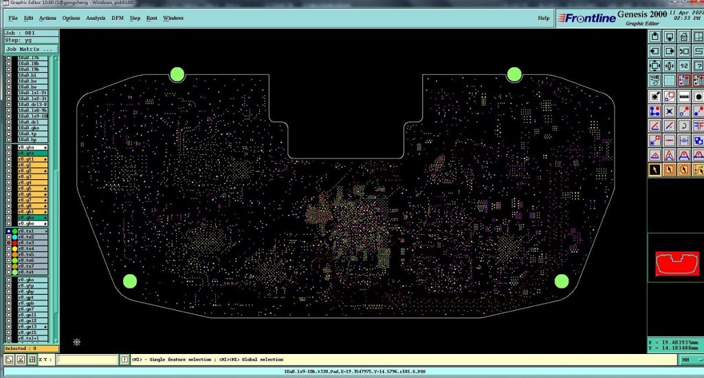
Centroid File
This is another important file that should never be ignored during PCB assembly. This tends to provide information about surface mount components on printed circuit boards. Centroid file in this case tends to provide information as well as orientation regarding such components. Please note that this file can sometimes be automatically generated by certain CAD packages. On the other hand, some packages do not.
Surface mount assembly may be handled by robots. However, these need the right files which will determine where components should be placed. This is where centroid can prove to be very crucial during the process of PCB assembly. When it comes to placing surface mount components, this plays a very important role. Just as said above, it helps in describing the position of such components. There are some important components of a centroid file which you should know. These are:
- X & Y position (location)
- Reference designator
- Rotation
- Foard’s side (bottom and top)
Reference Designator
This is what will get your Bill of Materials (BOM) as well as printed circuit board markation marked.
Layer
This could be bottom or top and doesn’t have to be the CAD designator. “Top” will be used in indicating the board’s top (part of it). Also, “Bottom” will indicate the board bottom part. In most cases, assemblers will use “Top” to mean the component’s side. The solder side will be indicated by “bottom”.
Rotation
This tends to go counterclockwise for every part that is on top. For parts that are bottom, the movement will be clockwise.
Location
The location simply requires the origin of the parts should be centred in the part. The board is going to have an origin that is indicated by O, O. This can be found on the board’s left corner.
The Files Required For PCBA PCB Assembly
| Files Required | Specification |
|---|---|
| Gerber files* | Gerber files in the format of RS-274X for PCB fabrication |
| BOM file* | BOM file in excel format for components sourcing and PCB assembly. It should include the basic information for each component: Reference Designators, Quantity, Manufacturer Part Number, Description, etc. |
| Pick & Place file* | Also known as Centroid file or XY data. It describes the position and orientation of all the surface mount parts, and it can help us quickly program the SMT assembly machines. |
| Assembly drawing (If you have) | It includes the positions and polarities of the components designators which can help us better understand your assembly needs, correct some ambiguous or even mistaken placements, and ends up with an excellent job. |
| Testing Guide & Test Fixtures (If you have) | To ensure the board’s quality, if you have a simple test guide for your PCBA boards that we can do, please let us know, and we can test all the boards before shipping. |
| Programming files & Programming tool (If necessary) | We could do IC programming for our customers if required. |
What Files Are Needed For Final Inspection And Test?
The inspection part is the most critical when it comes to manufacturing printed circuit boards. This is because the entire board will be tested or checked to know whether it has met the industry standard. There are several tests being carried out in this stage in order for the results to be validated. These are visual tests, and manual and x-ray inspections. Each of these tests is to ensure different parameters are measured.
KLARF File
The KLARF file is usually the result of automated optical inspection (AOI). This inspection is used in carrying tests on printed circuit boards in a bid to find defects like short circuits and open circuits. AOI is used during the manufacturing and assembling of boards.
In this case, such a circuit board will be scanned by a machine vision. The goal is for defects to be spotted. There are two problems that AOIs will usually detect. These are cases related to:
- Missing components
- Catastrophic failures
Once the inspection process has been completed, KLARF will be produced to show all the findings. This is what will determine whether or not a PCB has been built according to stipulated standards within the electronic industry.
Final Thoughts
In conclusion of the above, it can be seen that there are numerus files being used during the manufacturing and assembly of printed circuit boards.