Metal Core PCB, MCPCB Manufacturing Service
High quality, quick turn Metal Substrate PCB, Metal Backed PCB and Multi-layer Metal Core PCB Prototype Fabrication with Advanced Manufacturing Process.
Your reliable MCPCB manufacturer in China.
Home » PCB Manufacturing » Metal Core PCB
Most PCBs use a thick FR4 core layer to provide structural stability and interior copper layers for a multilayer printed circuit board. If problems like excessive heat and low thermal dissipation are required in your particular application, you might consider designing with a metal core PCB.
JHYPCB
A metal core PCB (MCPCB) is also known as a thermal PCB or a metal-backed PCB. The MCPCB has a metal material as a base instead of the FR4 materials as the heat spreader part of the PCB board. With our 12 years of PCB Manufacturing experience, state-of-the-art PCB manufacturing equipment, extensive PCB manufacturing expertise, and experienced professionals, we can provide you with high-quality metal core PCB manufacturing services.
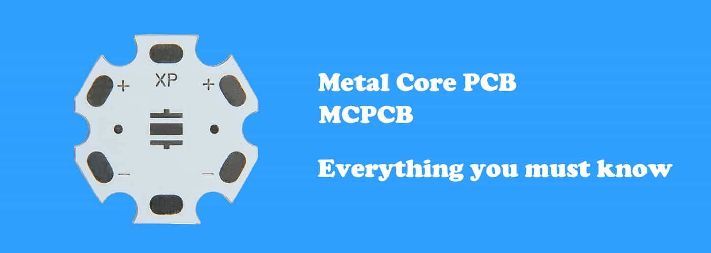
Everything you must know about metal core PCB
What is MCPCB?
What is a Metal Core PCB (MCPCB)?
A metal core PCB is a special PCB having a metallic base layer. This base layer is usually made of aluminum or copper. As it contains a metallic layer, it is named Metal Core PCB (MCPCB).
The metallic layer present in the metal core PCB does many wonders along with the dielectric layers. These PCBs are far better than FR-4 PCBs in terms of bearing thermal and pressure stresses. They are suitable for extreme conditions and high heat-dissipating components. Therefore, it has solved many issues that were faced in other PCB substrates. Metal core PCBs have tons of benefits, but all of them come at an additional cost.
Advanced Learning:
Why Metal Core PCBs?
- Metal core PCB can work normally in extreme environments
When it comes to high-temperature and high-pressure in the place or area where the PCB will be installed, it is important to make the decisions carefully. Typically, the FR-4 or common PCB substrates have some constraints and limitations. They cannot work under high pressure and temperatures as they cannot bear these extreme conditions. For instance, if you exert too much pressure on the FR-4 PCB, it will break, and in the case of high temperatures, it starts to bend and deteriorate with time. Thus, we cannot use every PCB in every situation. The condition of the environment must be kept in mind while selecting a PCB.
- Metal core PCB can withstand high temperature and high pressure
The pressure and temperature constraints of FR-4 are a serious issue. But thanks to the Metal Core PCBs. The solution to all problems of FR-4 and other similar materials is a metal core PCB, and it has gained much popularity in the industry. Nowadays, you see metal core PCBs in LED lights, automobiles, medical equipment, communication devices, and many other applications because of their characteristics and ability to bear high temperature and pressure.
- Metal core PCBs are much stronger than FR-4
Metal core PCBs have a layer of metal, usually aluminum or copper, and sometimes iron. Due to the presence of a metal layer, these PCBs are much stronger than FR-4. They can bear more pressure stress; therefore, they are commonly used in places where there is more vibration and high-pressure stress. The PCB retains its shape and does not break.
- Metal core PCBs also have an excellent temperature bearing capacity
They can work under extreme temperatures. They are mostly used in applications where the components dissipate heat. These PCBs can easily dissipate the heat and increase the life of the components. The PCB never bends due to high temperatures and offers excellent reliability. If we compare the heat dissipating capacity of the Metal core PCBs with FR-4, then metal core PCBs are 6-9 times better.
Layers of Metal Core PCBs
Metal Core PCB Stack up
The metal core PCBs have some special layers compared to the traditional FR-4 PCBs. The total number of all layers in the PCB also depends on the number of conductive layers you need.
Metal core PCBs can be of one, two, or multiple conducting layers. Their design and material make the PCB more durable, reliable, and long-lasting. There can be several layers, but they can be categorized into three types.
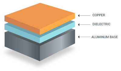
The types of layers in a metal core PCB are,
- Copper Layer (Conductive)
- Dielectric Layer
- Base Layer
This is the first layer, which is common in all PCBs. The copper layer is a conductive layer that transmits the signals. It is also known as the circuit layer as the whole circuit or conductive paths are made through it. Therefore, it is the same layer you will find in other PCBs.
The thickness of this layer depends on your requirements. You can select the thickness of this layer according to your project.This is an extremely important layer in a metal core PCB. You will not see this layer in FR-4. We know that the top layer is the copper layer, and the bottom layer is the base layer, which is made from metal. These two layers are conductive, and the insulation between them is the dielectric layer. Thus, this layer plays a very important role in separating the copper layer and the metal layer. It prevents short circuits.
The most vital function of the dielectric layer is the dissipation of heat. The layer has the ability to take heat from the components on the top layer and pass that heat through itself to the metallic base layer. Then, the metallic base layer dissipates the heat. Due to this layer, heat dissipation becomes more efficient as it can improve the heat dissipation up to 9 times. Thus, a metal core PCB is 6-9 times better than the traditional FR-4 PCB. There can be different components on the board, and their heat will be easily dissipated through this layer. Thus, it keeps the component cool and increases their life. Keep in mind that the thickness of dielectric in the metal core PCBs should be as minimum as possible. Usually, it is no more than 0.003-0.006 inches. Thus, it won't affect the overall thickness of the board. The reason behind the thin layer of dielectric is to transfer the heat in the shortest possible time. The transfer of heat depends on the thickness of the dielectric and the material. There are different dielectric materials available, and every material has a different heat transferring capacity, which is mentioned in Watts per Meter per Kelvin (W/mK).The base layer of metal core PCBs is made of metal, which is why the PCB is named as metal core PCB. As the base layer is metal, it can withstand more pressure stress and vibrations compared to FR-4 PCBs. It is strong, durable, and long-lasting.
The metal layer of the PCB works like heat sinks. It takes the heat from the conductive layers and disperses it to keep the PCB cool. Such cooling cannot be attained using cooling fans, so metal core PCBs enjoy more importance. The base layer can be of different metals. However, the most commonly used metals are copper and aluminum. Iron is also used in a few cases. Some buyers also request brass and other alloys. In the LCD industry, the preferred metal is aluminum as it offers a reasonable cost. On the other hand, copper is superior in performance, but it is costly. The thickness of the base depends on the customer's requirements. Typically, the thickness is in the range of 1-4mm, or it can be as you like.Layer Stack-ups in Metal Core PCBs
Metalcore PCB has three series, using magnetic materials, namely aluminum-based copper clad laminate, copper-based copper-clad laminate, and iron-based copper clad laminate. Compared with aluminum substrates, iron substrates have significant differences in hardness, manufacturing process, and difficulty. Metalcore PCB is divided into single-sided metal core PCB, double-sided metal core PCB, multilayer metal core PCB, and its thickness are between 1mm-6mm. Metalcore PCB also has a circuit layer, and the thickness of the circuit copper foil is between 1oz and 8oz.
The metal core PCB comprises a metal layer, a conductive layer, and an insulating layer. Among them, iron is used as the metal layer material, and copper foil is the conductive material. The insulating materials for the insulating layer are polyester or ceramics, modified polystyrene Ether, PI, prepreg, etc.
Learn more about Guide to Multilayer PCB Layer Stackup and thickness
Single Layer Metal Core PCB Stack up
This is obviously the simplest of all, and it has one layer of all three types of layers. At the top, it has a copper layer to create the circuit. Then, there is a dielectric layer, and finally, the metal base layer.
Advanced Learning:
The Most Important Things You Need To Know About Single-layer PCB
Double Layer Metal Core PCB Stack up
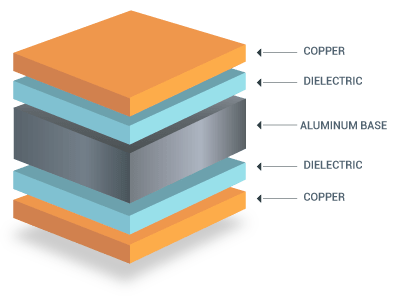
When we talk about a double-layer PCB, the first thing that comes to mind has two conductive layers. These two conductive copper layers are on both sides of the PCB. There are two circuit layers and two dielectric layers, while a metallic base layer is sandwiched between them. In total, there will be five layers,
- Copper Layer
- Dielectric Layer
- Metallic Base
- Dielectric Layer
- Copper Layer
Thus, this stack-up is also quite simple and used in many applications where you need the components on both sides.
Learn More Double-Sided PCB Manufacturing Process
Multilayer Metal Core PCB Stack up
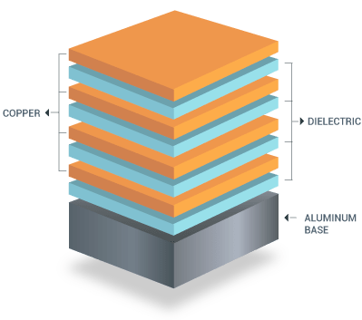
Multi-Layer PCB means the PCB that has three or more layers. The stack-up of the PCBs remains the same whether you have three layers, five layers, or more, but the number of dielectric and copper layers increases. The top layer is the copper layer, and then there is a dielectric layer. We have alternate layers of copper and dielectric. All layers with the dielectric and copper layer are connected. Finally, there is a base layer in the end.
The general stack-up can be given as,
- Copper Layer
- Dielectric Layer
- Copper Layer
- Dielectric Layer
- Copper Layer
- Dielectric Layer
- …
- …
- …
- Base Layer
In this type of stack-up, you can only use the component on the top copper layer. The other copper layers are to implement the complex circuits through vias.
Metal Core PCB Design
Important Design Guidelines for Metal Core PCBs
Metal core PCBs require specific design guidelines to pass through the standard metal core PCB manufacturing process.
Many essential design guidelines in a metal core PCB should be considered when creating a stackup with a metal layer. Metal-core boards are usually built with the metal layer used as a core layer in a low-layer count stackup.
Metal core PCB design (including DFM) follows many of the same basic design rules as typical PCBs on FR4. Metal core PCB boards carry specific manufacturing requirements, but a suitable design company can help you deal with these requirements and ensure that your board can be mass-produced.
About the design points of metal core PCB, this article will tell you more.
Metal Core PCBs VS FR-4
Metal core PCBs transfer heat 8 to 9 times faster than FR-4 PCBs, These metal core laminates keep the heat-generating components cooler by dissipating heat faster. The dielectric material is kept as thin as possible to create the shortest path from the heat source to the metal backing plate. This assists in quicker heat dissipation. The dielectric material thickness will usually range from 0.003″ to 0.006.”
The metal core PCBs are different in many aspects as compared to the common FR-4 board. Both boards have their own benefits, pros, and cons, which is why we cannot declare any of them the best. It depends on the customer’s requirements.
The electrical conductivity of metal core PCBs and FR-4 PCBs is the same as long as the conductive layer is made of the same material. If the conductive layer is copper, both PCBs will transmit signals similarly. There won’t be any effect on electrical conductivity.
In the case of thermal conductivity, there is no doubt that the metal core PCB is the winner. It is because there are an extra dielectric layer and the signature metal layer. The heat of components is transferred to the metallic layer through the dielectric layer. Thus, it can bear more temperature stress. Even under high-temperature stress, there is no need to worry about the breakage and deterioration of the board.
In contrast, the FR-4 PCBs are suitable when there are no or a few high heat-dissipating components. If there is any high heat-dissipating component, it is used with a heat sink.
If the heat dissipation in the circuit is not up to the mark, the components do not last for a long time. They deteriorate, and finally, you need to replace them to get the desired results. Moreover, the FR-4 board cannot bear high-temperature stress. It starts to bend with time.
On the other hand, metal core PCBs work exceptionally well under high-temperature stress. They can easily dissipate the heat without the need for the heat sink. Their metallic base acts as a large heat sink.
The durability of the PCB matters a lot when there is high-pressure stress. There can be vibrations in the final product. FR-4 can bear little vibrations to an extent, but for high-pressure stress, metal core PCBs are considered the best. The metal is much stronger than the epoxy board, which is why it is more robust and works in extreme conditions.
It is quite easy to cut down the FR-4 board into pieces and sizes you need. However, the metal core PCBs are quite hard. Metal core PCBs cannot be cut down with equipment used for the FR-4 PCBs. Usually, special blades are used that are coated with diamond.
When it comes to single-layer boards, FR-4 can use any type of component, whether it is a through-hole component or SMT package. It is because the leads of the through-hole components can easily be passed from the board via drilling, and they are soldered on the other side as the board itself is an insulator.
The single-layer metal core PCBs can only work with SMDs as they can be mounted over the surface without drilling. They cannot accommodate through-hole technology because the leads of the components will touch a common conductor, which is the metallic base. Thus, it will result in short circuits.
If we look at the FR-4 and metal core boards, we won’t find any safety hazards at all. But the actual judgment can be made on their performance. When the components on the FR-4 boards are hot, they create a safety hazard; therefore, it is necessary to cope up with this problem. Otherwise, there can be a fire in the result.
On the other hand, the components on the metal core PCBs always remain cool, so they do not pose a safety hazard.
It is quite obvious that the price of the metal core PCB would be high as the metal is more expensive than the epoxy resin. The price of the metal core PCBs also depends on the metal. The cheapest one is iron, and then comes aluminum. Copper is more expensive. These are the commonly used metals, but there can be other alloys and metals as well.
In metal core PCBs, more components are placed on the area as there is no heat sink on the board. It offers more space. Furthermore, the cost of heat sinks and cooling fans is also saved.
| Parameters | Metal Core PCB | Standard Fr4 PCB |
| Conductivity | High thermal conductivity, about 1W/mK to 7W/mK | Low thermal conductivity, about 0.3W/mK to 0.4W/mK |
| Thermal Relief | Metal core PCB dissipates heat quickly. | Heat transfer rate is lower. |
| Thickness | Limited thickness variations | Wide range of thickness |
| Plated Through Holes | Plated Through Holes isn’t available for single layer Metal Core PCBs. | All FR4 PCBs use Plated Through Holes. |
| Machining Process | V-score must use diamond-coated saw blades. | Uses the regular machine processes |
| Solder Mask | Solely White color solder mask available for only the top. | Dark color solder mask available for both bottom and top. |
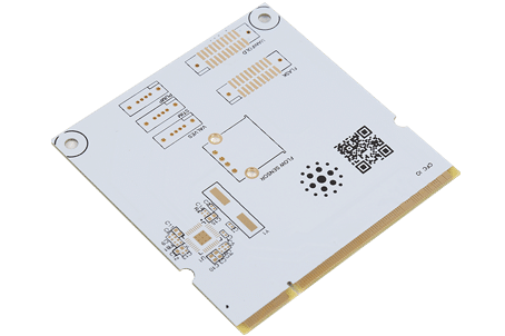
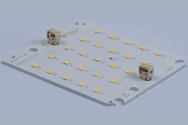
China Metal Core PCB Fabrication
Metal Core PCB Manufacturing Service
With our professional technical knowledge and experienced personnel, we can provide you with first-class metal-core PCB solutions. Whether it’s metal core PCB prototyping or high-volume production, we’ve got you covered. Choose JHY as your metal core PCB manufacturer and supplier, and we also meet your requirement for fast turnaround time. No matter how many quantities you need, we promise fast turnaround times.
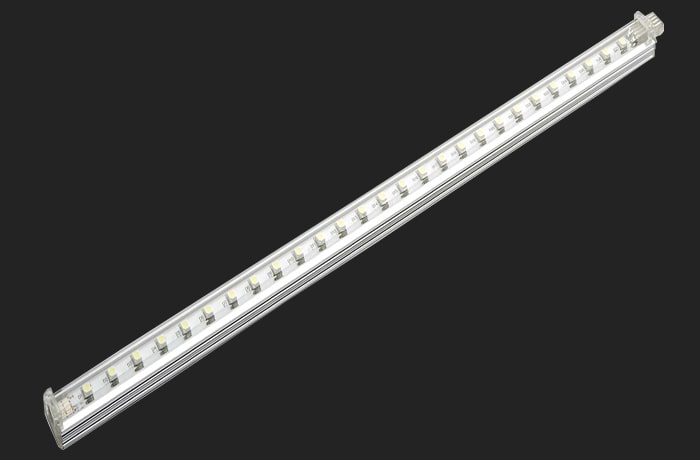
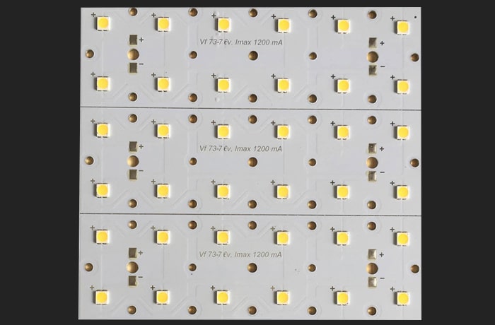
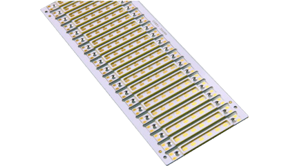
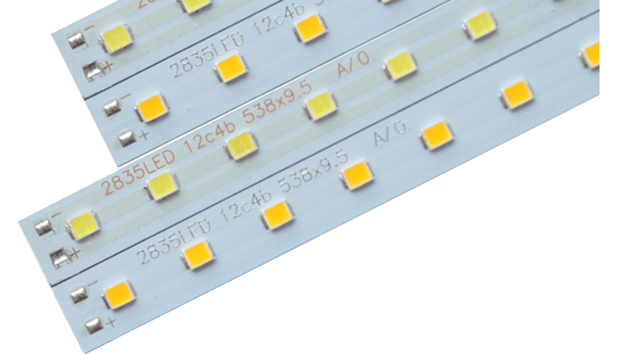
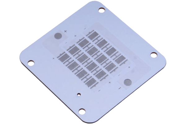
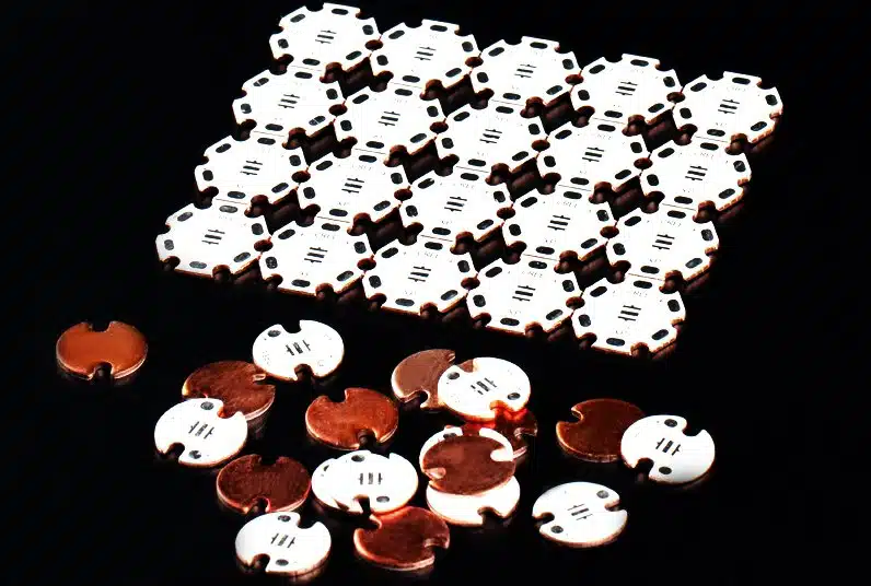
LED Metal Core PCB Supplier
JHY is a professional PCB supplier in China offers high quality LED metal core PCB fabrication service. Our strong PCB manufacturing strength can customize all kinds of high reliability printed circuit boards for you.
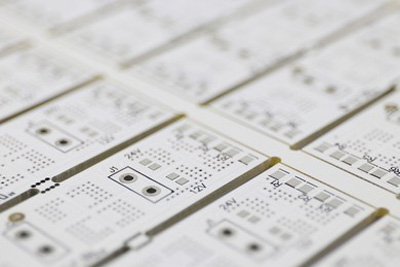
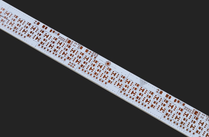
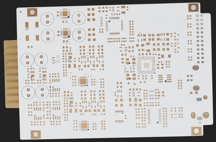
Metal Core PCB Prototype
Order IMS, MCPCB or metal core PCB from your trusted PCB manufacturer in China, JHY is your best choose. JHY offers low-cost metal core PCB and quick turn metal core PCB prototype fabrication service with the best service.
Learn more about our:
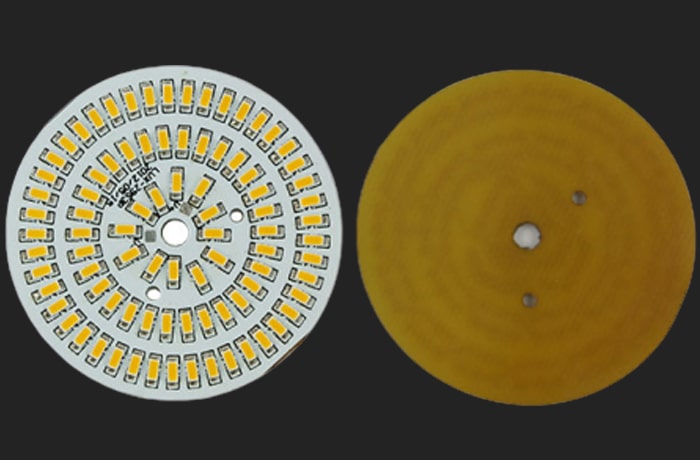
Metal core aluminum PCB is an aluminum-based copper clad laminate with good heat dissipation function. Generally, the single layer aluminum-based PCB is composed of a three-layer structure, which is a circuit layer (copper foil), an insulating layer and a metal base layer. Also used for high-end use is designed as a double sided and multilayer aluminum PCB.
Copper-based PCBs use copper as a primary base material in place of commonly used FR4. The copper base material is then covered with an insulating layer followed by a circuit layer. Copper core/based PCBs are known to have excellent heat dissipation and can be used for high frequency applications with minimal variation in performance over wide temperature ranges. However, these advantages do come at a cost, Copper Core PCBs are very expensive.
Metal-backed PCB
The metal layer is placed on the back side of the board, and the components are on the opposite layer. Traces cannot be routed on the back layer, although through-holes can route between dielectric layers and bring the ground to the metal layer.
Single Layer Metal Core PCB
The single layer MCPCB features a thin dielectric layer separating a copper foil and a metal base layer. The dielectric layer serves two functions—it provides the electrical insulation between the copper foil and the metal base. Furthermore, it also acts as a good thermal conductor for removing heat from hot SMD components on the copper foil and dissipating it into the metal base. Most single layer metal core PCBs feature aluminum or copper as their metal base.
Double Sided Metal Core PCB
The structure of a double layer metal core PCB resembles that of a regular double-layer PCB board. It has two copper foils separated by a prepreg. One of the copper foils has a metal core on its side, with a thin dielectric layer separating the two. Thermal vias in the board carry heat from hot SMD components on the top copper foil to the metal core. The lower copper foil only acts as signal traces connecting SMD components on the top side.
Multilayer Metal Core PCB
The structure of multilayer metal core PCBs is similar to that of regular multi-layer PCBs. The board typically has more than two copper foils separated by prepreg layers. The position of the metal core may vary. Depending on the application, some boards may have the metal core on one of the extreme sides, just as in a double layer metal core PCBs. However, some PCBs may also have the metal core in between, with copper foils on either side.
Metal Core PCB Surface Finishes
JHY offers a wide range of surface finishes to ensure that the metal core PCB is well protected in the environment that it has to be deployed. The vast majority of the MCPCB use HASL LF. And if there are no fine pitch components, BGAs, then HASL LF is probably the most suitable finish for power LED assembly. Yet, nothing would stop us to propose also all other surface finish; OSP, immersion gold/Tin/Silver for your metal core PCB applications.
MCPCB / IMS PCBs Solder Mask
Most customers requiring IMS PCB boards select a white or a black solder mask. This is probably related to the fact that we want to either absorb or reflect the LEDs light. But from a technical point of view, we are able to apply green, red or any other solder mask colour.
The following is our metal core PCB fabrication capability:
| Feature | Technical Specification |
| Material | Aluminum core, FR4 prepreg, Copper, Iron Alloy |
| Board Thickness | 0.8mm-10mm |
| Thermal Conductivity | 0.8, 1.5, 2.0, and 3.0 W/m.K. |
| Max Panel size | 21*33inch |
| Copper Thickness | Out Layer: 8oz; Inner Layer: 6oz |
| Surface Finish | OSP, HASL lead-free, chemical gold, Immersion Gold/Tin/Silver |
| Solder Mask | White, Black, Blue, Red, Green |
| Silkscreen Color | Black, White |
| Inspection Methods | 100% Visual Inspection, Cross Sectioning, Sample Lot Inspection, Electrical Testing |
| Packing | Vacuum/Plastic bag |
Learn more about PCB fabrication capability
Metal Core PCB Manufacturing Process
The metal core PCB fabrication process is ①Grinding plate (500# brush)→②Washing→③Passivation→④Washing×3→⑤Blow-drying→⑥Drying. Grinding plate: Grinding the iron surface only, grinding the plate according to FR4 parameters.
Metal core PCBs must follow a particular process due to the presence of the metal layer in the stackup. If the board is a single-layer board with no layer transitions back to the metal plate, then the standard FR4 dielectrics can be used, where the dielectric layer is pressed and bonded to the metal plate.
For multilayer dielectric stackups, the metal core must first be drilled to allow for a layer transition without creating a short circuit. First, slightly larger holes are drilled into the metal layer, and the holes are plugged with an insulating gel. This gel is cured and hardened, allowing it to be plated with copper, just like a standard via. The rest of the stackup is pressed and bonded with the metal layer, and through-holes are drilled through the stackup, followed by plating and cleaning.
The first board must check the circuit without scratches, black tin surface, other defects, and uniform wear marks.
Learn more about Metal Core PCB Manufacturing Process
Metal Core PCB Manufacturer in China
One Place for All Your Metal Core PCB Needs - JHYPCB
JHYPCB is a leading manufacturer of PCBs and PCBAs in China. Our large facility can handle small-large volume orders without the restriction of the minimum pieces; you can also order one PCB. We offer quick PCB prototypes and turnkey PCB assembly services. Everything can be done under one roof, and we take responsibility for every process. Our experts are always ready to help you develop better designs for better performance.
We guarantee high-performing PCBs with exceptional quality at a low cost. We have a strict quality management system certified by RoHS, IOS, and UL. We follow the industry standards, and our latest technology makes everything more reliable and faster. You can contact us anytime, and our 24/7 customer service team will help you out.
Metal Core PCB FAQs
Metal core printed circuit boards (MCPCB), also known as thermal PCB, have a metal material, such as aluminum, metal, or copper, as their base as opposed to the traditional FR4. The purpose of the metal is to divert heat away from critical board components towards less crucial areas, such as the metal heat sink backing or the metallic core.
Metal core PCBs or MCPCBs use metal as the base material, which can even work in high temperatures. These PCBs are made from Aluminium, copper, or a mixture of alloys. Usually, Aluminum and Copper are used as the metal core PCB material.
Metal core PCB offers a great list of benefits when an application requires excellent heat dissipation.
- High Heat Transfer—Heat transfer depends on the conductivity of the metal layer.
- Easy to Fabricate—Fabrication process is similar to regular PCBs.
- Lightweight—Aluminum core PCBs are lighter than boards with ceramics.
- Longer Lasting—Metal substrates are longer-lasting and more thermally conducting than epoxy products.
- Recyclable—Metal products are recyclable and non-toxic.
- Vibration Resistant—Boards with metal cores can resist vibration better and are suitable for use in high vibration applications.
Metal Core PCBs with their high thermal conductivity permit an effective transfer of heat. They are, therefore, extensively used in:
- High current applications
- Power LEDs
- SMD
- Power Circuit Boards
- Traffic lights
- Automotive lighting
- General lighting
- Photovoltaic
The thickness of metal cores in PCB base plates is typically 30 mil – 125 mil, but thicker and thinner plates are possible.
MCPCB copper foil thickness can be 1 – 10 oz.
Helpful Resources
- Choosing the Right Metal Core PCB Manufacturer is Critical to Your Success
- IPC Standards: A Guide to Standards for PCB Manufacturing and Assembly
- How To Search for a Reliable PCB Manufacturer
- Why Choose Chinese PCB Manufacturer
- The Cheapest PCB Prototype Manufacturer-Your Best Choice
- Introduction to the aluminum PCB manufacturing process