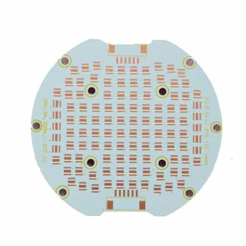
Summary: The common thermoelectric separated copper core PCB is composed of a copper foil, insulating layer, metal substrate, thermal interface material, heat sink, and some other components. The circuit part and the thermal layer are distributed differently in the circuit layer; therefore, in order to ensure good contact between the heat dissipation part and the thermal layer part, the copper substrate PCB needs to be strictly controlled. This article first introduces the advantages of using copper-based PCB and then focuses on the preparation and experimental process of thermoelectric separated copper core PCB.
In order to ensure the effective use of copper core PCB in the field of heat dissipation, it is necessary to clarify the significance of using thermoelectric separated copper substrates PCB. After understanding the advantages of its use, corresponding measures can be taken to strengthen the use of copper substrates in the industry. Master the production method of thermoelectric separation copper-based PCB, according to its operating characteristics. Timely consider how to solve the problem and enhance the understanding of the function of thermoelectric separation copper core PCB. Pay attention to the application of copper-based PCB in the industry, and quickly grasp the technical points in the production of thermoelectric separation copper core PCB, which will help to promote the wide application of thermoelectric separation copper core PCB in the field of LED heat dissipation.
1 Advantage of the Use of Copper core PCB in Heat Dissipation
The use of copper core PCB in heat dissipation is mainly due to the advantages of thermoelectric separated copper core PCB. The benefits are high density, strong heat dissipation, and zero thermal resistance between the circuit part and the lamp bead contact part. It effectively extends the life of the lamp beads because of the high power and heat-carrying solid capacity of the copper base material. Tin spraying, immersion gold, silver plating, etc., can be effectively treated according to actual work requirements to ensure the effectiveness of surface treatment.
2 Using Experimental Methods to Explore the Application of Thermoelectric Separated Copper Core PCB
2.1 Experimental Equipment
You need to select cast copper alloy plates, dry film, developer, solder paste, and other materials. At the same time, gather anti-corrosion potions and special experimental equipment, such as scanners, heat and cold shock test chamber, tester, adjustable cold and temperature device, and anti-radiation system. All materials and equipment should be ready for experimentation.
2.2 The Production Process
- Step 1: Use the light drawing template to perform effective file processing by the requirements of the drawings and parameter settings.
After that, perform the corresponding imposition, film production, washing, development, cleaning, and air drying operations on the files in sequence.
After air drying, check carefully whether the film is damaged and strengthen the protection of the film. Perform effective copy processing on quality negatives, and then check the copied diazo film.
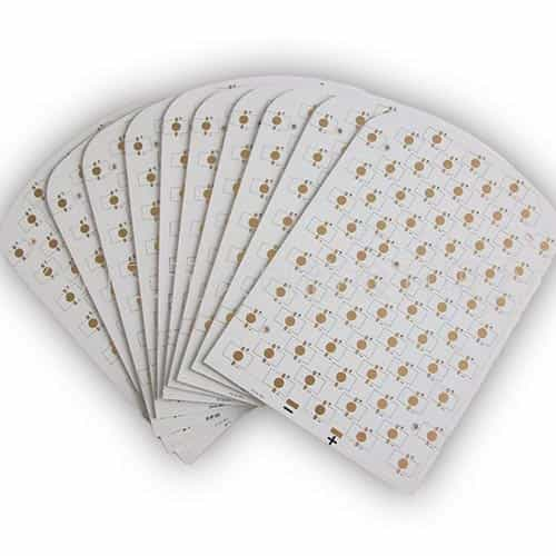
- Step 2: Make the copper core PCB. Please select the appropriate copper-aluminum composite substrate according to the size of the cutting board, and use a special slicer to cut it into copper foil and film. The pre-pressing treatment is carried out with a plastic machine and turned into a nail hole. The baler is used for peripheral protection, and the burr treatment is carefully carried out to ensure effectiveness.
- Step 3: Groove the adhesive part and sequentially polish and brush the surface of the composite substrate. After pickling and printing, baking can be carried out to align the diazo sheet with the pattern of the composite substrate. Adjust the thickness of the surface metal according to the set parameters, and retain the metal protrusions. Check the cleanliness of the adhesive after slotting to ensure that the slotting depth is appropriate for use in the thermal pad.
- Step 4: Place the grooved part of the back glue on the thermal pad, and perform effective cold pressing and edge grinding.
- Step 5: Perform development processing on the combined plate, remove the turbid part of the surface after processing, and then check the correctness of the circuit to facilitate automatic drilling of the thermal pad.
- Step 6: Finally, the combined board is firmly fixed on the CNC milling machine, and then after high pressure, drying, and other treatments, the finished thermal conductivity copper base PCB is obtained.
2.3 Test
Pressure Resistance Test:
During cold pressing operation, ensure that the ambient temperature is 180°C, the pressure is 62kg·cm -2, and the optimal pre-pressing time is 60 minutes. The test must be carried out in time to ensure the quality of copper substrate production.
When the working pressure is stable, the humidity is controlled at 65% to 80%. The pressure is maintained at 100kPa; the thermoelectric separation copper core PCB test is carried out by hot and cold washing to detect its thermal shock. A person conducts 500 thermal shock tests at a low temperature of -55°C and a high temperature of 120°C with a residence time of 18 minutes and a temperature change of 2 minutes, thereby improving its cold and hot pressure resistance to a greater extent.
Thermal Resistance Test:
The ordinary copper core PCB and the thermoelectric separation copper core PCB are compared in the thermal resistance test. In this link, it is found that the thickness of the insulation layer of the thermoelectric separation copper core PCB and the ordinary copper core PCB is 1.1mm and 1.5mm, respectively. In the thermal resistance test, to prevent the testing effect from affecting regular use, the void rate during welding needs to be controlled at 15%, the ambient temperature and humidity are effectively adjusted, and the temperature control system is used to improve the accuracy of the test results, such as using a temperature tester. The temperature of the entire system is detected, and the tested sample’s heat resistance and thermal resistance performance are judged according to the overall heat dissipation performance of the LED module system.
2.4 Experimental Results
Micro-observation Method:
Using the micro-observation method, we learned the structure design of the copper core PCB in time. After pre-compression, the metal heat conduction part of the copper base PCB is in good contact with the circuit layer. It is determined that the metal heat conduction column is the best heat source placement point. According to the corrosive observation, the metal heat conduction part is step-shaped; both sides are arc-shaped and is partly covered by dry film. The etching solution slowly etches the metal heat conduction part along the horizontal direction and finally reaches the specified height of the heat column.
Heat Dissipation Effect:
The use of the copper substrate PCB mainly depends on its heat dissipation function. So, it is essential to test the heat dissipation function. By observing the changes in temperature and time, you can understand the actual situation of constant temperature to understand the differences in lamp beads caused by time changes.
In the heat dissipation efficiency analysis, the experimenters clarify the influence of module power, radiation power, forward working voltage, working current, and other things on the heat dissipation effect of the thermoelectric separated copper core PCB in time. In repeated practice, it is found that the thermoelectric effect is different due to the difference in the LED model and module. When using an ordinary copper core PCB, the junction temperature of the LED chip is 72.41℃. However, using the thermoelectric separated copper core PCB link, the test shows that the junction temperature of the LED chip is 48.72℃. When using a standard copper core PCB, the thermal resistance of the module is 4.24℃/W. However, after using a thermoelectric separated copper base PCB, the overall thermal resistance of the module is 2.13℃/W.
Due to the different material properties, the thermal resistance of the module thermometer at the bottom of the substrate is further. According to thermal resistance and copper substrate PCB heat conduction theories, the bottom of the copper core PCB is the primary carrier for heat diffusion. There is a specific thermal resistance on the surface of the metal layer and the insulating layer. Due to the significant interfacial impurity defects, some heat is dissipated, and the phonons are in the insulating layer. The continuous spreading between them changes the direction of heat flow. The greater the heat conduction power, the higher the thermoelectric separation copper core PCB’s light extraction efficiency and the more stable performance.
3 Conclusion
It is also necessary to actively understand the application process of the thermoelectric separation copper core PCB and prepare the corresponding thermoelectric separation copper base PCB to enhance the understanding of LED heat dissipation. Mainly, explain the preparation process, performance test, and heat dissipation efficiency of the thermoelectric separated copper substrate PCB. Judge the heat resistance of the tested sample according to the overall heat dissipation performance, observe the changes in temperature, time, etc., and compare the common copper substrate with the thermoelectric separation copper core PCB. It helps to realize the thermoelectric separation of copper core PCB and the ordinary copper base PCB. Thermoelectric separation copper core PCB has advantages in module thermal resistance and chip temperature.
JHYPCB is a reliable metal core PCB Manufacturer that offers Aluminum PCB, LED PCB, and SMT PCB assembly services. Feel free to contact us at sales@pcbjhy.com.
Advanced Learning:


