Before, we introduced the main steps of PCB assembly in detail but did not elaborate on the process of SMT (Surface-mount technology). Today we will introduce the SMT process and precautions in detail.
SMT is a link with the highest degree of automation in the modern electronic assembly industry. An SMT line only needs 5-7 operators to keep it running, and a PCB can be assembled about every 30-60 seconds.
SMT PCB Assembly Process
00. Shop Floor Tracking Number
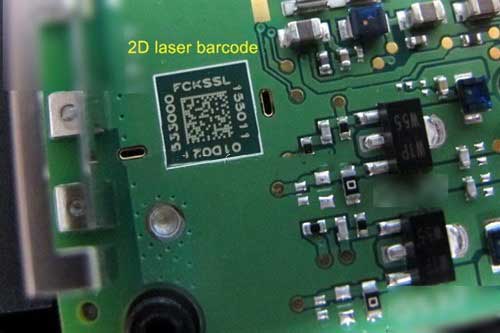
The pre-operation of the SMT production line must be to print the tracking barcode on the bare board first so that the PCBA factory’s Shop Floor Control System (SFCS) or Shop Floor Data Collection System (SFDC) can track the production quality of the PCBA. There are several options for printing PCBA tracking barcodes: label paper, inkjet printing, and laser printing.
With the advancement of technology, PCBA tracking barcodes have also evolved from the original one-dimensional barcodes to two-dimensional barcodes. The two-dimensional code improves the information capacity of the barcode and reduces the area of the barcode relatively.
The following conditions must be met when printing PCBA tracking barcodes:
1) The barcode will not affect the appearance of the product or mislead customers;
2) The barcode must be clear, and the information can be read with a scanner;
3) The barcode must be able to withstand a certain amount of friction and be stored for a long time.
01. Bare Board Loading
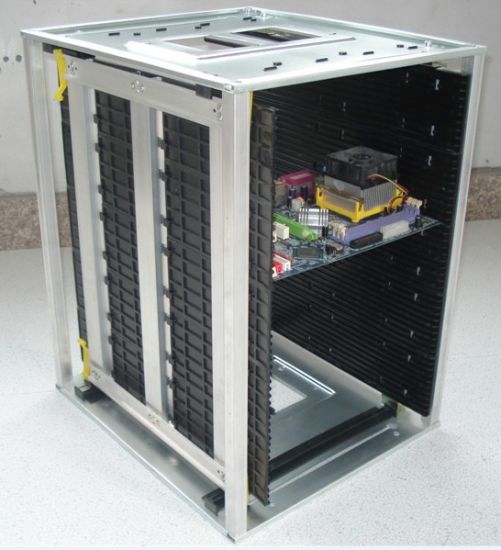
The first step in PCB assembly, of course, is to load the Bare Board onto the SMT assembly line. At present, the most common technique is to arrange the Bare Boards neatly and overlappingly and place them on the material rack, and then send them to the conveyor belt of the SMT production line piece by piece from the top board by a mechanical device. This mode of operation sometimes causes slight scratches on the board’s surface during the transfer of the PCB board, so sometimes the Bare Board is also placed in the magazine (magazine) so that there will be no damage when the bare board is transferred.
The whole process will be sent to the computer by the sensor, and then judge when to push the board and give instructions when to stop pushing the board.
02. Solder Paste Printing
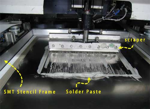
The first job of the printed circuit board entering the SMT assembly line is solder paste printing.
Solder paste printing prints solder pastes on the pads of the PCB parts to be soldered through SMT Stencil. The location and amount of solder paste will affect the subsequent soldering quality. These solder pastes will melt in the high-temperature zone of the reflow oven in the subsequent SMT process and solder the electronic components to the circuit board during the re-solidification process.
The primary purpose of using solder paste as the combination of electronic parts and PCB is:
1) Before the soldering is completed, the electronic parts are pasted and fixed on the circuit board so that they will not be offset due to the movement and vibration of the PCB. This is also why the solder paste is in the form of a paste.
2) After reflowing at high temperature, the electronic parts are soldered and fixed on the PCB to not fall off during the use of the end-user and achieve the purpose of electronic signal transmission.
03. Solder Paste Inspection, SPI
The quality of solder paste printing will directly affect the quality of subsequent parts welding. Therefore, most of the leading SMT manufacturers now set up an additional optical instrument to check the quality of solder paste printing after solder paste printing for stable quality. This instrument is called the Solder paste inspector. The principle is similar to AOI (Auto Optical Inspection). After inspection, if the board with poor solder paste printing is found, it can be selected first, washed off the solder paste on it, reprint the solder paste, or remove excess solder paste by maintenance.
SPI is so important because if the solder paste is solidified after reflow soldering, it must be repaired or scrapped with a soldering iron only after the solder paste is solidified and found to have soldering problems. If printing problems can be identified and improved or resolved before the solder paste cures, it can significantly reduce production defects and reduce maintenance costs.
04. Chip Placement, Pick and Place Speed Machine
The electronic parts on the circuit board are divided into active components (IC parts) and passive components (Inductors, Capacitors, Resistors, and other parts). SMD passive components (small resistors, capacitors, inductors) are also known as Small Chips. The SMD passive parts only two terminals need to be soldered, so the relative positional accuracy requirements when placing these small parts on the circuit board are also Higher, so a fast/high-speed placement machine (Chip Placement Machine) was designed. This type of placement machine generally has several nozzle heads, the speed is breakneck, and several parts can be placed in one second.
At this time, the paste-like advantage of solder paste is revealed because when the parts are placed, the nozzles usually only move up and down, and the alignment of the parts depends on the precise movement of the board. These electronic parts that have been placed on the circuit board will be stuck by the solder paste that has just been printed on the circuit board, so even if the parts are placed very fast (the speed of the board is also very fast), the parts on the board Not even being thrown away. However, large parts or heavy parts are not suitable for processing by a fast placement machine. One is that it will slow down the pick and place speed, and the other is that the parts will shift from their original positions due to the rapid movement of the board.
An SMT production line generally has 1-4 fast placement machines.
05. Pick and Place General Machine
This general-purpose pick and place machine is also known as a “slow machine.” It can be applied to almost all SMD parts pick and place requirements. Still, because its appeal is not speeding but pick and place accuracy, all slow-speed machines are generally used to pick and place some larger or heavier, or For multi-pin electronic parts, such as BGA, connector, card reader, shield, etc., because these parts need more accurate positions, all their alignment and angle adjustment capabilities become very important. After picking, first, use the camera to take a picture of the appearance of the part, and then adjust the position and angle of the part to place it, so the overall speed is relatively much slower.
Because of the size, the electronic parts here may not always have tape-on-reel, and some may be tray or tube packages.
The traditional pick and place machine uses the suction principle to pick and place electronic parts, so a clean surface must be reserved on the top of these electronic parts for the suction nozzle of the pick and place machine to pick and place parts. Some electronic parts have no plane for these machines. It is necessary to customize special nozzles for these special-shaped parts add a layer of flat tape to the parts.
06. Hand Place Component or Visual Inspection, or AOI before reflow oven
When all the parts are on the board, there is usually an inspection station before entering the high-temperature reflow oven. The role of the inspection station is to check the placement of parts for misplaced or missed defects. Because if there is a welding problem after the reflow, it must be repaired with a soldering iron, but this will affect the quality of the product, and there will be additional costs. Other parts that cannot be operated by pick and place machines, such as larger electronic parts or DIP/THT parts or some special reasons, will also be manually placed here.
In addition, some SMT assemblies of printed circuit boards for mobile phones are equipped with an additional “AOI” process before the reflow oven to confirm the quality of the parts before reflow soldering. Another situation is that some boards will directly solder the Shielding-can to the circuit board at the SMT stage. Once the shielding-can is placed on the circuit board, the soldering quality cannot be by through AOI or visual inspection.
07. Reflow
The purpose of Reflow is to melt the solder paste and form the IMC between the component pins and the circuit board, that is, to solder electronic components to the circuit board. The temperature profile of the rise and fall of the temperature often affects the soldering quality of the entire circuit board. The general reflow oven will set pre-heat, soak, Reflow, cool zone according to solder characteristics to achieve the best solder effect.
Taking the current lead-free soldering process SAC305 solder paste as an example, its melting point is about 217°C, which means that the temperature of the reflow oven must be at least higher than this temperature re-melt the solder paste. In addition, the maximum temperature in the reflow oven should not exceed 250 °C; otherwise, many parts will be deformed or melted because they cannot withstand such a high temperature.
After the circuit board passes through the reflow oven, the entire circuit board assembly is complete.
08. Auto Optical Inspection (AOI)
Although AOI after reflow oven has almost become the standard configuration of SMT today, not every SMT production line will be equipped with Auto Optical Inspection. One of the purposes of AOI after setting up a reflow oven is to replace it with AOI because some circuit boards with too high a density cannot be effectively used for the subsequent open-short test (ICT). However, because AOI is an optical judgment, it has inherent blind spots, such as the solder under the parts cannot be inspected. There will be shadow effects near the high parts, which cannot be effectively inspected. At present, AOI can only inspect the parts that can be seen: Tombstone, side stand, missing parts, displacement, polarity direction, empty welding, etc., but cannot judge fake welding and BGA welding, properties, resistance value, capacitance value, inductance value, and other parts quality. Some AOIs cannot even inspect the side solder of QFN or Castellated terminations.
Therefore, at present, AOI cannot wholly replace ICT and FVT.
Therefore, if only AOI is used to replace ICT, there will still be a great risk in quality.
09. Unloading
When the PCB board is assembled, it will be returned to the magazine. These magazines have been designed to allow the SMT machine to automatically pick and place the board without affecting its quality.
10. Visual Inspection
Whether or not an AOI inspection station is set up, a general SMT production line will also set up a visual inspection area for circuit assembly boards. The purpose is to check whether there are any defects after the circuit board is assembled. If an AOI inspection station is set up, the number of visual inspection personnel can be reduced because some places that AOI cannot interpret are still to be checked. The current technology, AOI, still has a false-positive rate.
Many SMT factories will provide visual inspection templates to facilitate visual inspectors to inspect the weldability and polarity of some critical parts.
11. Touch up or wave soldering
If some parts cannot be used with SMT pick and place machine, it is necessary to hand solder the parts or use wave soldering or selective soldering to solder traditional through-hole parts. This step is usually placed after the SMT finished product inspection; the purpose is to distinguish the defect from the SMT or the post-SMT process.
Touch-up electronic parts use Irom and solder wire. When soldering, the soldering iron tip maintained at a specific high temperature is in contact with the pins and pads of the parts to be soldered until the temperature rises to a temperature high enough to melt the tin wire. The tin wire is added to melt, and the soldering iron tip is quickly removed to reduce the soldering temperature. After the tin wire has cooled and solidified, the parts will be soldered to the circuit board.
There will be some fumes generated when welding parts by hand, and these fumes will contain many heavy metals, so the operation area must set up fume exhaust equipment and try not to let the operator inhale these harmful fumes.
It should be reminded that the post-welding of some parts will be arranged in a later stage of the process due to the needs of the process.


