In the civilian and military UAV market, the demand for UAVs is increasing day by day, and the iteration cycle of UAV products is significantly shortened. Avionics systems, navigation systems, data link systems, power systems, etc. that are compatible with UAV systems have also gained high speed.
The internal hardware structure layout of the drone
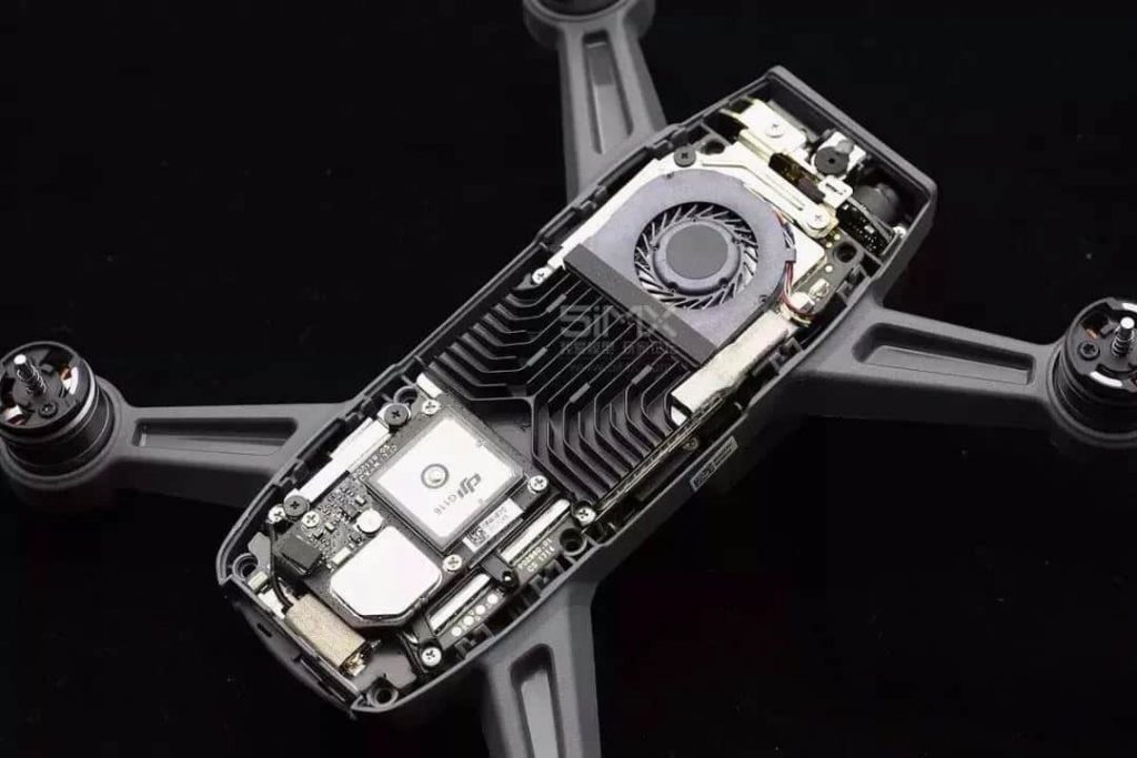
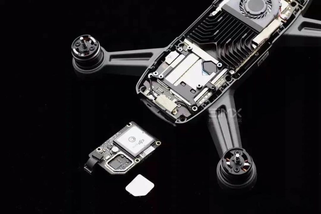
Take DJI’s Spark as an example. Spark’s hardware integration is very high. In the design of the internal structure, in addition to considering the rationality, the aesthetic considerations are also taken into account, which gives people a pleasant feeling. According to the interview with DJI engineers from the 5iMX evaluation room earlier, the most significant design challenge of Spark is to pack so many things into such a small space while taking into account cost, productivity, reliability, heat dissipation, shock absorption, Power efficiency, electromagnetic interference, radio frequency performance. When we look back on the R&D process through the actual photos of the finished product today, we can see that every detail is filled with wisdom and enthusiasm. This is indeed a commendable product.

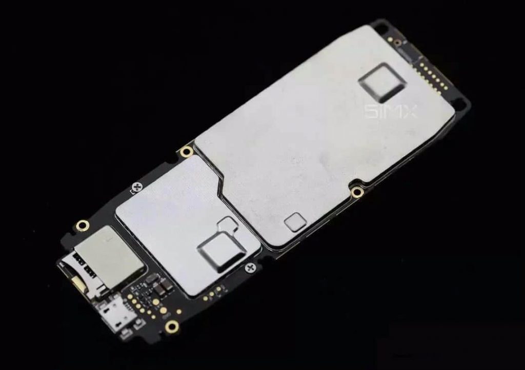
GPS module is an independent existence, it can be removed. Its back is the motherboard, and the motherboard is covered with an electromagnetic shielding cover.
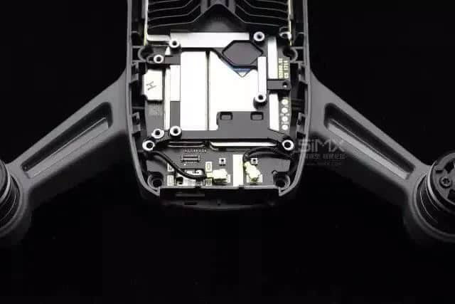
The right side of this part should be the high-frequency communication module of Spark. The two feeders are connected to the antenna, and the position of the antenna is on the side of the fuselage head.
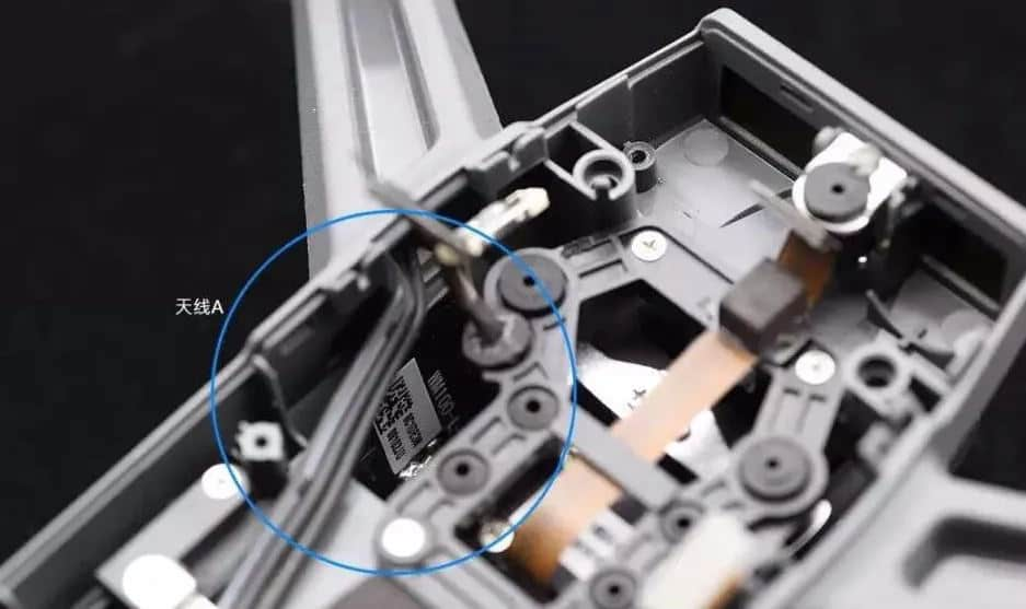
Spark’s antenna is a 2.4G signal. There are two antennas, located on the left and right sides of the front of the fuselage. The picture above shows the antenna on the left.
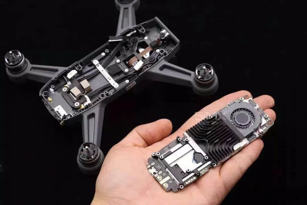
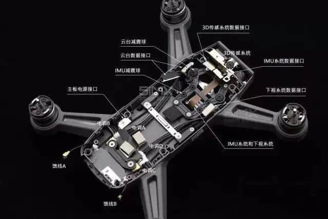
Spark’s body uses a one-time injection molding process, which means it is a complete whole, without screws and connections. Due to its lightweight, the structural strength of Spark’s fuselage should have a good drop resistance performance. However, it is best not to try an extreme flight, because once the fuselage is damaged, replacing it is a time-consuming and laborious project. There are detailed function descriptions on the pictures so that you can learn more about it.
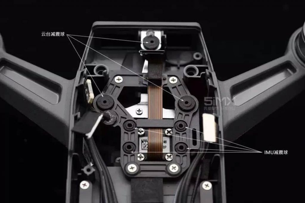
Spark’s gimbal camera uses 3 shock-absorbing balls; Spark’s IMU is an independent module that is placed in the fuselage at the back of the gimbal and suspended by 4 shock-absorbing balls. This design can ensure that the IMU is protected from electromagnetic interference and has an independent shock-absorbing device to make its work more stable and reliable.
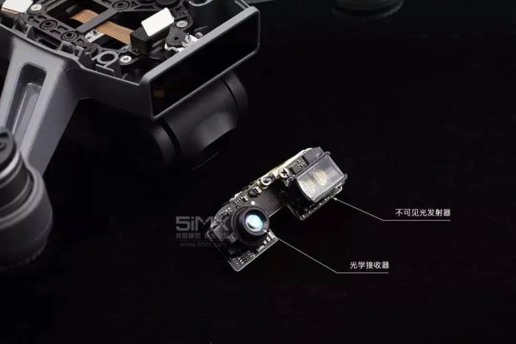
Front-view TOF module (depth camera), this module can be taken out of the body. In addition to collecting depth data, it can also color-collect gesture visual information in three-dimensional space. The receiver on the left is a particular camera. The transmitter on the right emits invisible light.
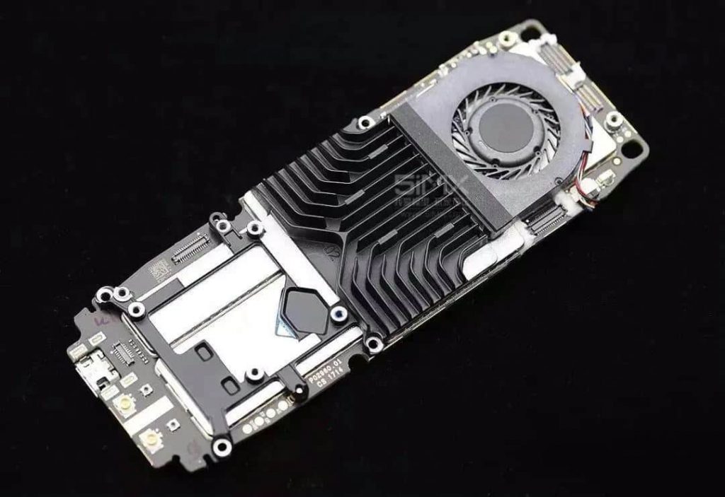
Motherboard front (GPS module removed). The layout logic is clear: the cooling fin is located in the middle of the motherboard, and its shape and direction are symmetrical beauty, and according to the heat intensity of the circuit unit and customized design, it can be said to be extremely ingenious. The lower part of the radiator fin body is the central heating unit. The diversion groove brings the airflow generated by the fan out of the cooling holes on both sides of the fuselage top cover. The secondary heating unit also obtains effective heat exchange due to the integral extension of the radiator fin and the intervention of the fan.
The integrated radiator is tailor-made according to the heating degree of the circuit and the height of the heating parts.
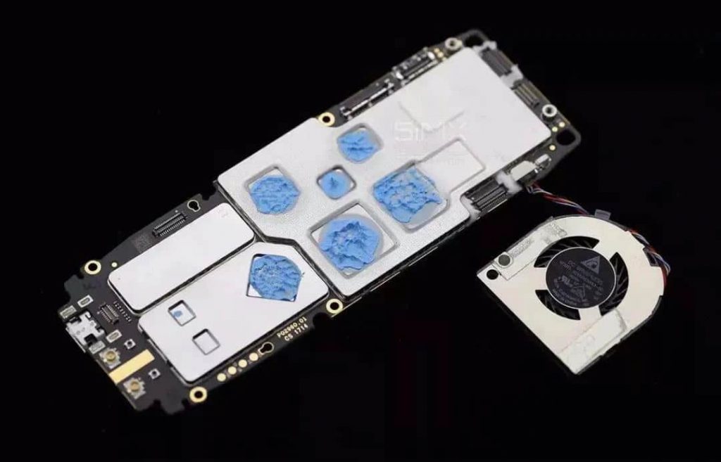
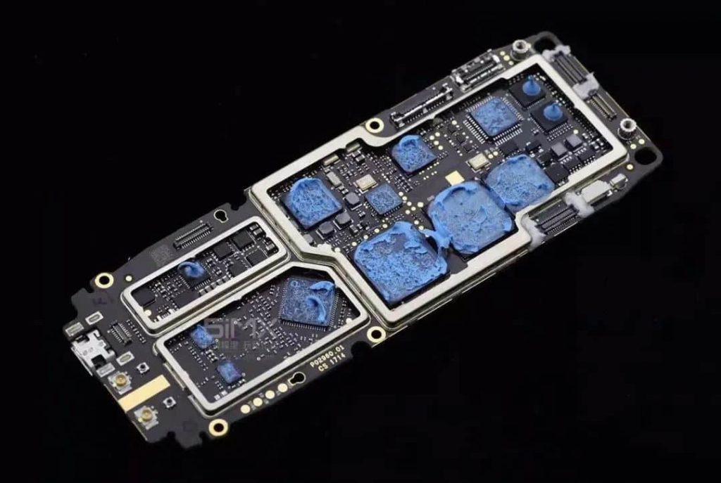
Remove the fan and radiator; it can be seen that the heating point is conducive to thermal grease (blue substance). To achieve an excellent electromagnetic shielding effect, all parts on the circuit board are electromagnetically shielded by the electromagnetic shielding cover according to the function of the unit.
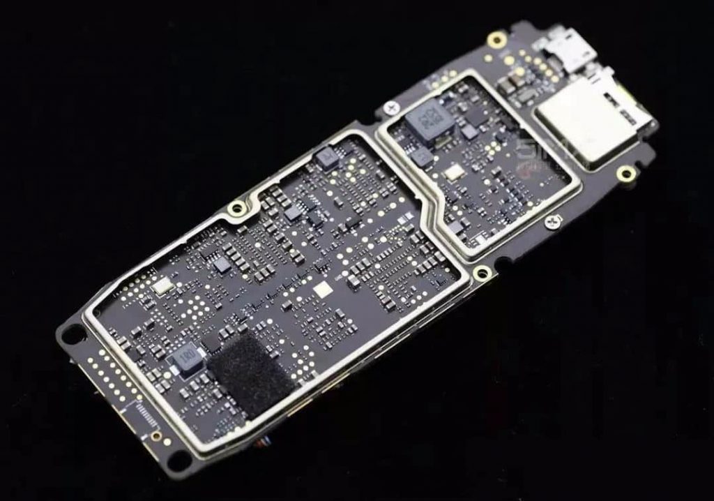
The back of the motherboard is also covered with a large electromagnetic shield.
Open the electromagnetic shielding cover, and it can be seen that this site is mostly resistors, capacitors, inductors, and other parts, which are shielded to ensure that there is nothing wrong.